Apparatus for forming a microlens mold

a technology of microlens and apparatus, which is applied in the direction of shaping cutters, manufacturing tools, instruments, etc., can solve the problems of low optical accuracy, low quality of inability to make high-quality optical surfaces in small sizes or arrays. achieve high sags, accurate optical surfaces, and high quality

Inactive Publication Date: 2005-01-25
EASTMAN KODAK CO
View PDF21 Cites 41 Cited by
  • Summary
  • Abstract
  • Description
  • Claims
  • Application Information

AI Technical Summary

Benefits of technology

The present invention has the following advantages: the precision microlens mold can be used to mold high quality, micro-sized optical articles, such as microlenses, that have symmetric surfaces with steep sides

Problems solved by technology

While these techniques work well for larger surfaces, they are not suited for making high quality optical surfaces in small sizes or arrays.
Other techniques are available for making small scale single lenses and arrays but they are limited as to fill factor, optical accuracy and/or the height or sag of the lens geometry that can be made.
However, the orbital motion and the grinding surfaces become impractical when making optical surfaces below a few millimeters in size.
Diamond turning can be used to make optical surfaces down to 2 millimeters in size but the setup is difficult.
Precise location of multiple optical surfaces is not possible due to multiple setups.
The need for multiple setups also increases the machining time for an array so that diamond turning becomes cost prohibitive.
While this technique can provide a near 100% fill factor, the second set of lenses does not have round contact

Method used


Image

  • Apparatus for forming a microlens mold
  • Apparatus for forming a microlens mold
  • Apparatus for forming a microlens mold

Examples


example 1

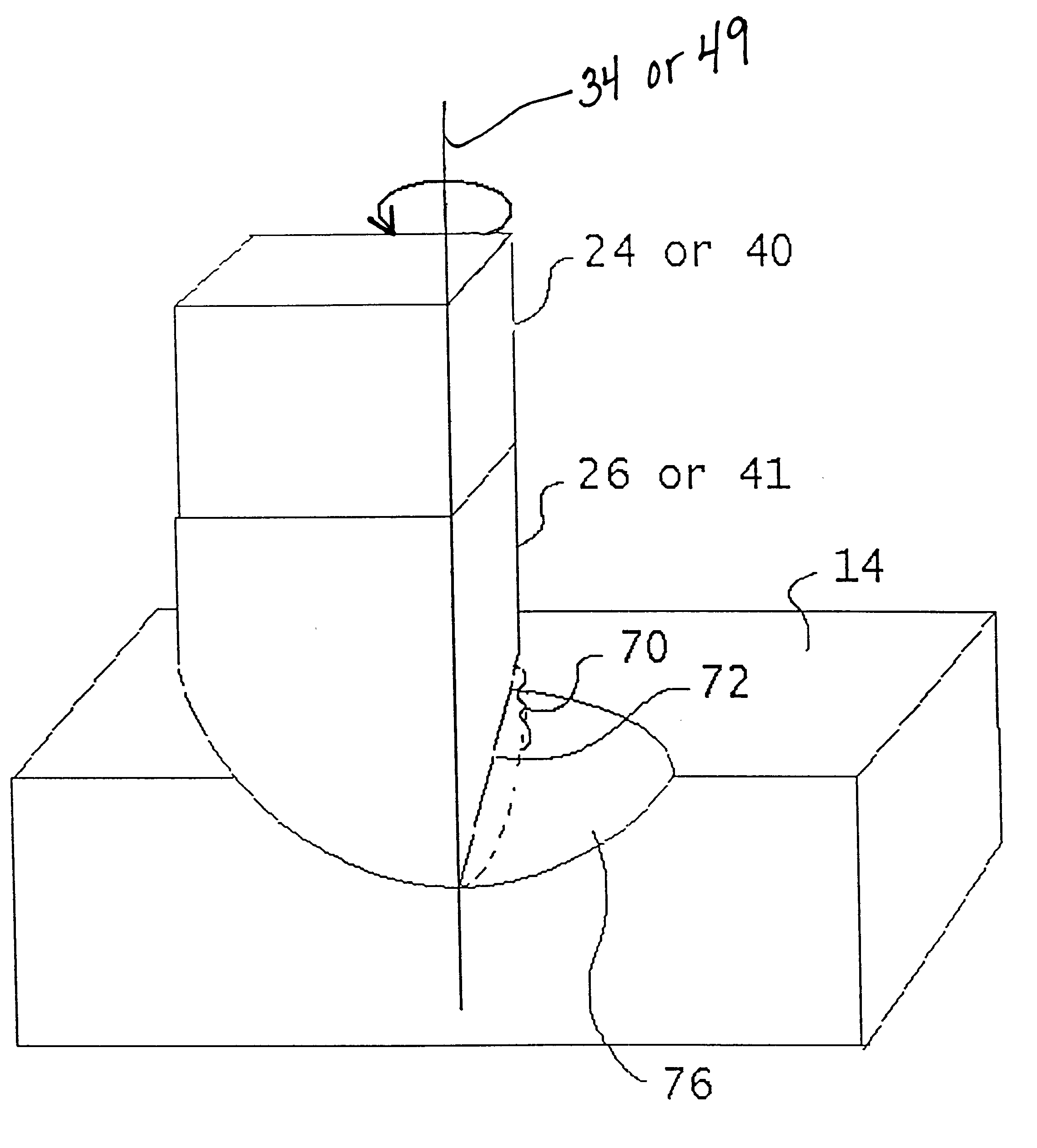
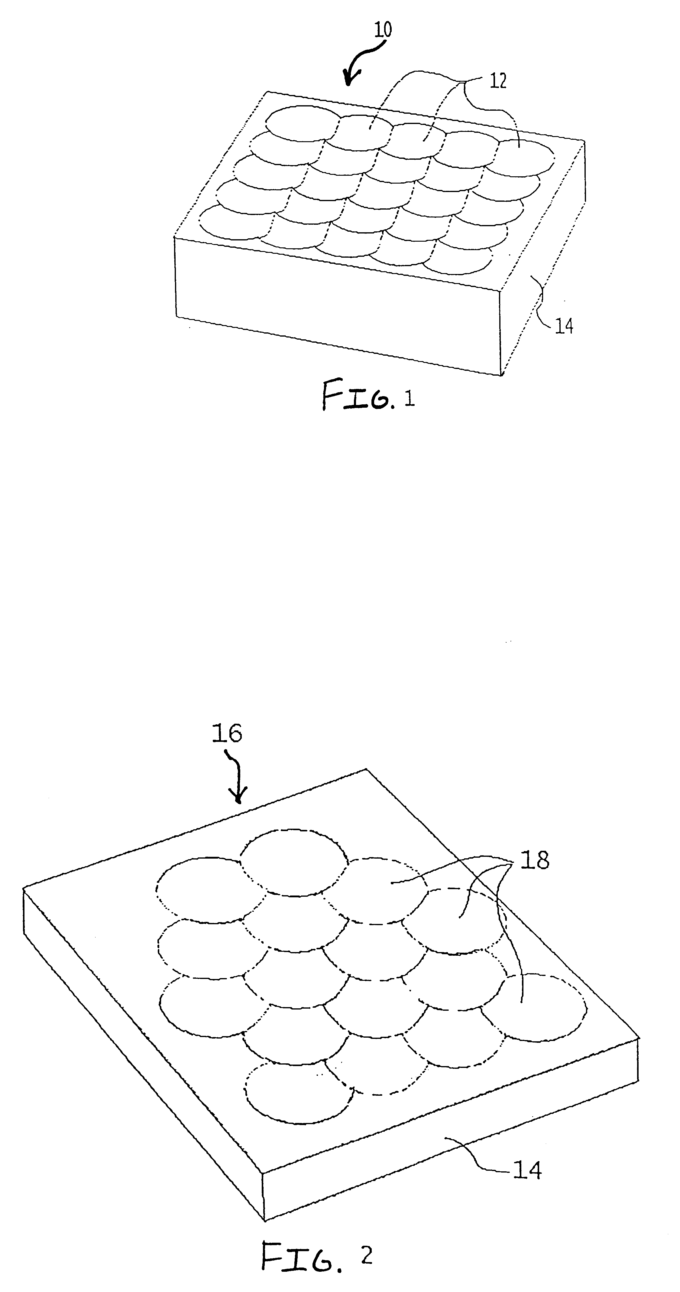
A microlens array mold with 80×80 microlenses was made in aluminum. The half radius diamond tool was obtained from ST&F Precision Technologies and Tools, located in Arden, N.C. The microlens surfaces were 0.250 mm across positioned in a square intersection array. The microlenses surfaces were spherical in curvature with a radius of 0.500 mm and a sag of 33 micron. Referring to FIG. 4, centering of the diamond cutting member 26 in the control member 36 was done using an iterative process where a test cut was examined under the microscope and adjustments of the location of diamond cutting member 26 were made based on the size of the center defect. Rotational speed of diamond cutting member 26 used was about 1000 rpm. Cutting fluid was purified mineral oil. The result of this process was a center defect of the machined mold of 2 micron and surface irregularity of 1 Wave (0.5 micron). Parts were subsequently injection molded, using the machined mold surface, to produce polymethylmethacr...

example 2

Similar to Example 1 with the exception that a hardened nickel-plated substrate was used for the machined mold surface.

example 3

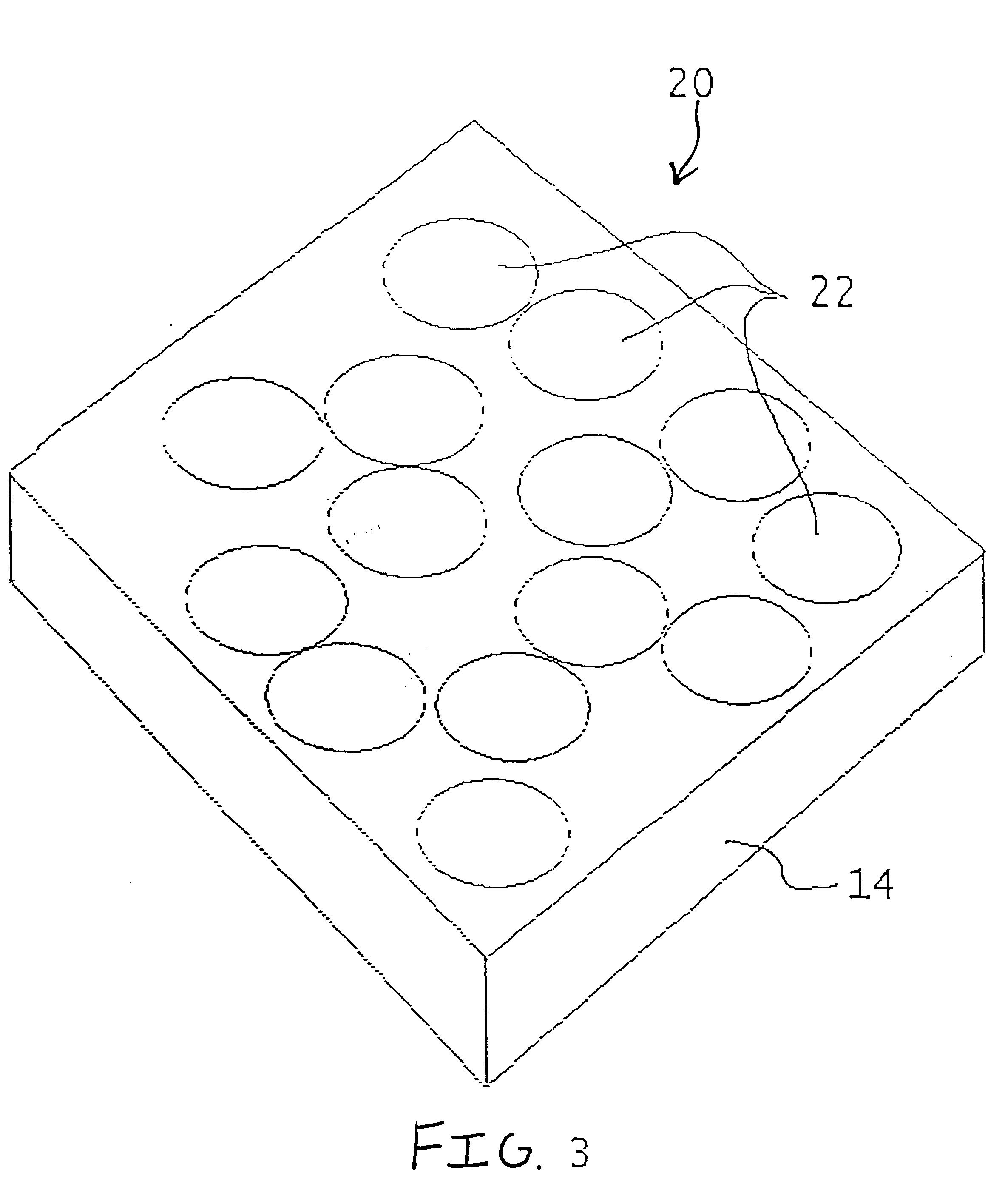
A microlens array mold with 13×13 microlenses surfaces was made in a hardened nickel-plated substrate. The microlens surfaces were 1.30 mm across positioned in a square intersection array. The half radius diamond tool was obtained from ST&F Precision Technologies and Tools, located in Arden, N.C. The microlens surfaces were spherical in curvature with a radius of 3.20 mm and a sag of 213 micron. Centering and the machining process were the same as described in Example 1. The result was a center defect of 1.5 micron with a surface irregularity of 0.30 Wave (0.15 micron).


PUM

PropertyMeasurementUnit
Lengthaaaaaaaaaa
Displacementaaaaaaaaaa

Abstract

An apparatus for making microlens molds and microlens array molds is described which utilizes a forming element having a rotating half radius diamond cutting member. A substrate is alignably arranged with the diamond cutting member so that the cutting member can mill a mold cavity in the substrate. The apparatus can be used to make high sag lens molds with high accuracy and a nearly 100% fill factor.

Description

FIELD OF THE INVENTIONThe invention relates generally to the field of improved microlens molds and microlens. More particularly, the invention concerns a method of making a precision mold suitable for forming high quality, micro-sized optical articles, such as a microlens or microlens array.BACKGROUND OF THE INVENTIONRotationally symmetric optical surfaces in molds for injection molding or compression molding are typically made either by grinding or diamond turning. While these techniques work well for larger surfaces, they are not suited for making high quality optical surfaces in small sizes or arrays. Other techniques are available for making small scale single lenses and arrays but they are limited as to fill factor, optical accuracy and / or the height or sag of the lens geometry that can be made.Grinding relies on an orbital motion of the grinding surfaces to make a precision optical surface without scratches. However, the orbital motion and the grinding surfaces become impracti...

Claims


Application Information

Patent Timeline
IPC IPC(8): B29D11/00B29C33/38B29L11/00G02B3/00
CPCB29D11/00442B29D11/00365B29D11/0048Y10T407/21Y10T409/309184Y10T407/1948Y10T409/305544Y10T407/27G02B3/00
Inventor BORDER, JOHNDAMBRAUSKAS, ROBERTSADLIK, CRAIG A.
Owner EASTMAN KODAK CO
Why Eureka
Try Eureka