Method and apparatus for varying the critical speed of a shaft

a critical speed and shaft technology, applied in the direction of liquid fuel engines, vessel construction, marine propulsion, etc., can solve the problems of compromising the ability to use these design solutions, affecting the design of the machine, and not being able to operate a rotating sha

Inactive Publication Date: 2005-01-25
GENERAL ELECTRIC CO
View PDF10 Cites 57 Cited by
  • Summary
  • Abstract
  • Description
  • Claims
  • Application Information

AI Technical Summary

Problems solved by technology

In most types of machinery, for example gas turbine engines, it is not allowable to operate a rotating shaft at its critical speed, particularly at its first bending mode, because of the potentially high levels of vibration that may result.
This requirement often places substantial constraints and compromises on the machine's design.
The ability to use these design solutions is compromised when the shaft in question runs concentrically through another shaft, since the inner shaft's length and diameter are constrained by the outer shaft and the surrounding “core engine” structure as, for example, is the case with the low pressure shaft or power shaft of a gas turbine engine.
The inner shaft of other devices, such as a turbofan engine, operates over a wide speed range (typically 25% to 100% of maximum RPM), and accordingly there is not a practical “transient” window in which to place the shaft's critical speed, thus requiring the shaft's critical speed to be placed above the maximum operating RPM.
Since the “core engine” structure limits the minimum shaft length and maximum shaft diameter, it may not be possible to achieve a feasible turbofan design, or the inner shaft requirements may impose significant operating life and weight penalties on the “core engine”.
However, prior art active bearing design does not change the effective length of the shaft, which limits the amount of change that may be obtained in the shaft's critical speed.

Method used


Image

  • Method and apparatus for varying the critical speed of a shaft
  • Method and apparatus for varying the critical speed of a shaft
  • Method and apparatus for varying the critical speed of a shaft

Examples


Embodiment Construction

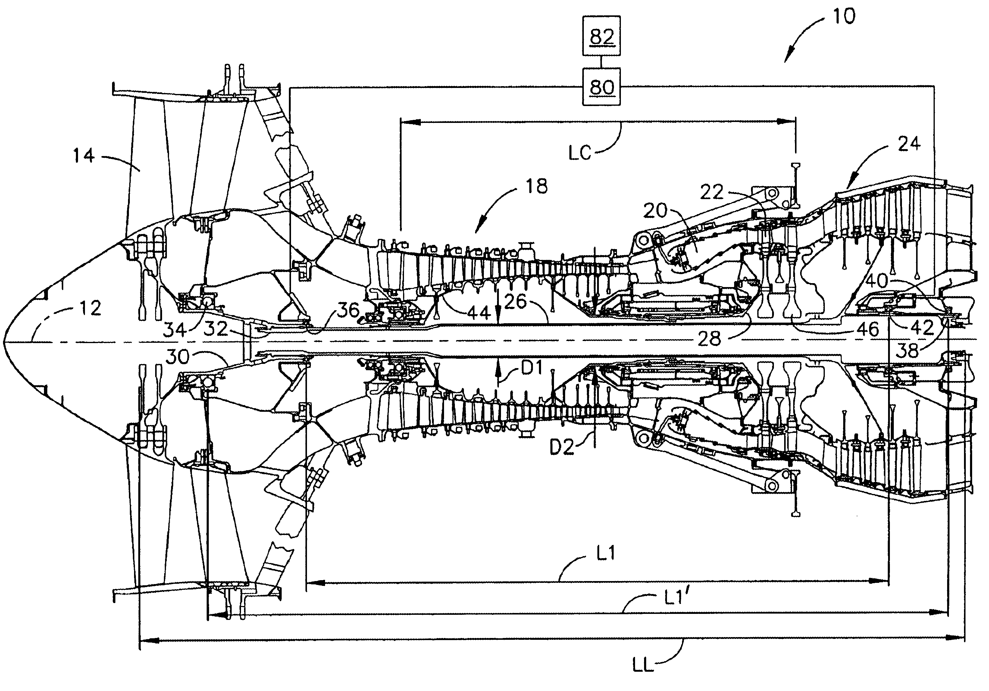
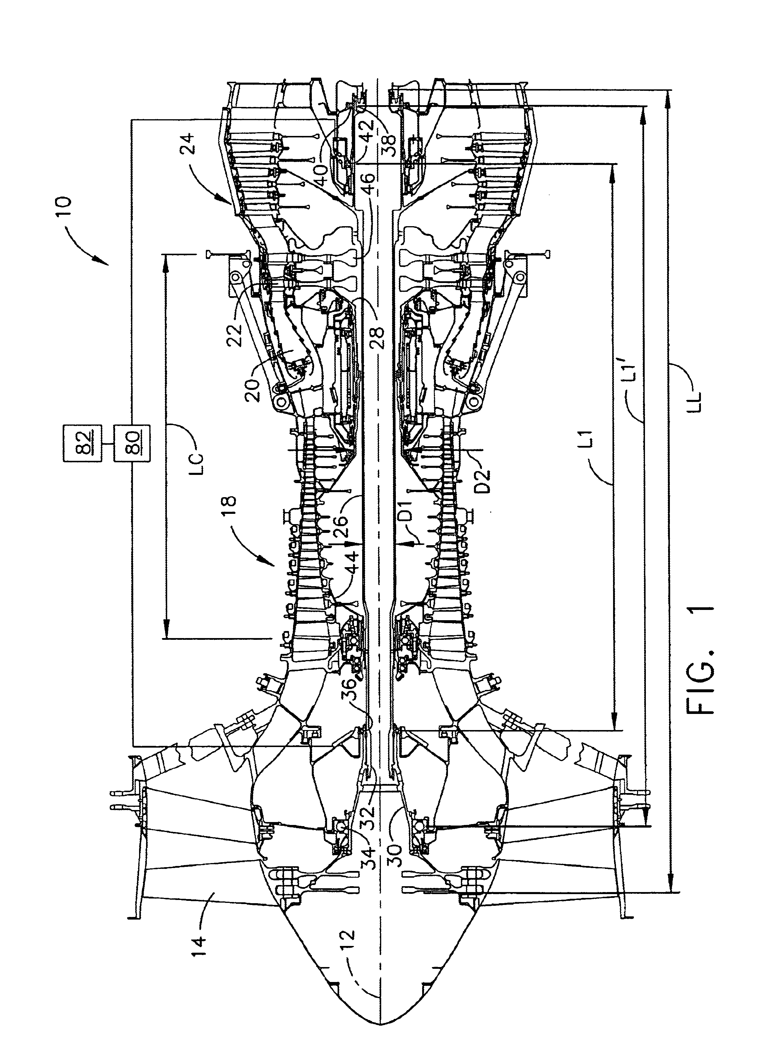
Referring to the drawings wherein identical reference numerals denote the same elements throughout the various views, FIG. 1 shows an exemplary turbofan engine 10 incorporating the critical speed modification system of the present invention. The engine 10 has several components in serial flow relationship along a longitudinal axis 12, including a fan 14, a compressor 18, a combustor 20, a high pressure turbine 22, and a low pressure turbine 24. The low pressure turbine 24 drives a low pressure turbine (LPT) shaft 26 which is splined to a fan shaft 30 that drives the fan 14. The high pressure turbine 22 drives the compressor 18 through a core shaft 28 that is mounted coaxially with and surrounds the LPT shaft 26.

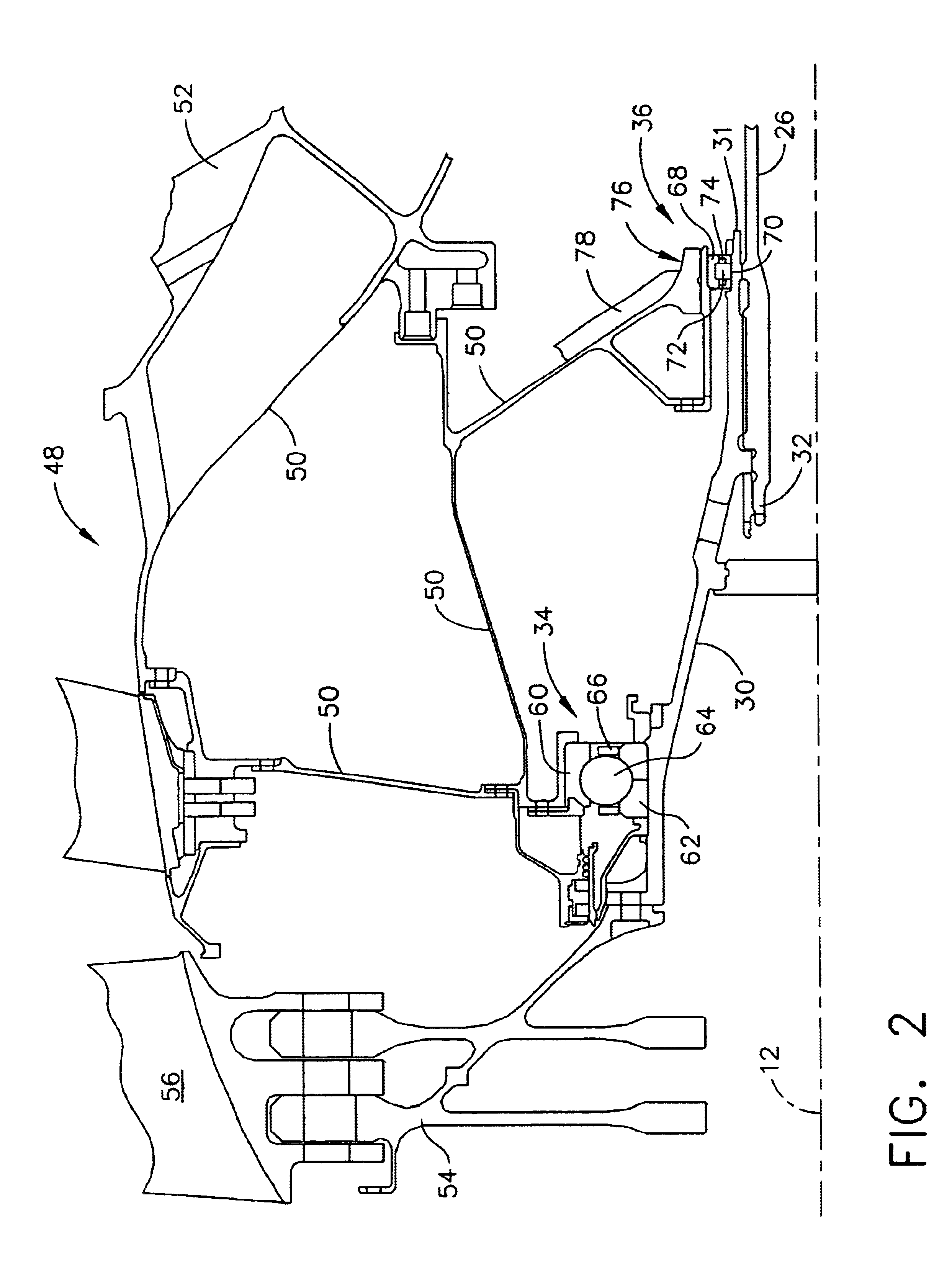
The LPT shaft 26 has a length LL and a diameter D1, and is mounted in a plurality of bearings, which are typically a combination of rotating element (e.g. ball or roller) bearings. In the illustrated example, the forward end 32 of the LPT shaft 26 is supported by a forward be...


PUM


Abstract

A system is provided for changing the critical speed of a shaft that includes: a first shaft supported for relative rotational movement with respect to a stationary structure, a forward bearing disposed at the forward end of the shaft, an aft bearing disposed at the aft end of the shaft, at least one active bearing disposed between the forward bearing and the aft bearing, and means for changing the support stiffness of the active bearing.

Description

BACKGROUND OF THE INVENTIONThis invention relates generally to rotating shafts and more particularly to methods of controlling the critical speed of a rotating shaft.In most types of machinery, for example gas turbine engines, it is not allowable to operate a rotating shaft at its critical speed, particularly at its first bending mode, because of the potentially high levels of vibration that may result. This requirement often places substantial constraints and compromises on the machine's design.Prior art turbofan engines use a shaft diameter that for the shaft's length is sufficient to place the shaft bending critical speed above the shaft's maximum operating speed. Other methods of controlling the shaft's critical speed include using multiple shaft bearings such that the shaft's effective vibration length is reduced and the boundary conditions are sufficiently stiff to also place the critical speed above the operating range. The ability to use these design solutions is compromised...

Claims


Application Information

Patent Timeline
Patent Type & Authority Patents(United States)
IPC IPC(8): F01D25/16F16C27/04F16C27/00F02C7/06F16C19/52F16C19/00F16C19/26F16C19/54
CPCF01D25/164F16C27/04F16C19/52F02C7/06F16C19/54F16C2360/23
Inventor HULL, PETER RICHARD
Owner GENERAL ELECTRIC CO
Why Eureka
Try Eureka