Encapsulated permanent magnet motor rotor
- Summary
- Abstract
- Description
- Claims
- Application Information
AI Technical Summary
Benefits of technology
Problems solved by technology
Method used
Image
Examples
Embodiment Construction
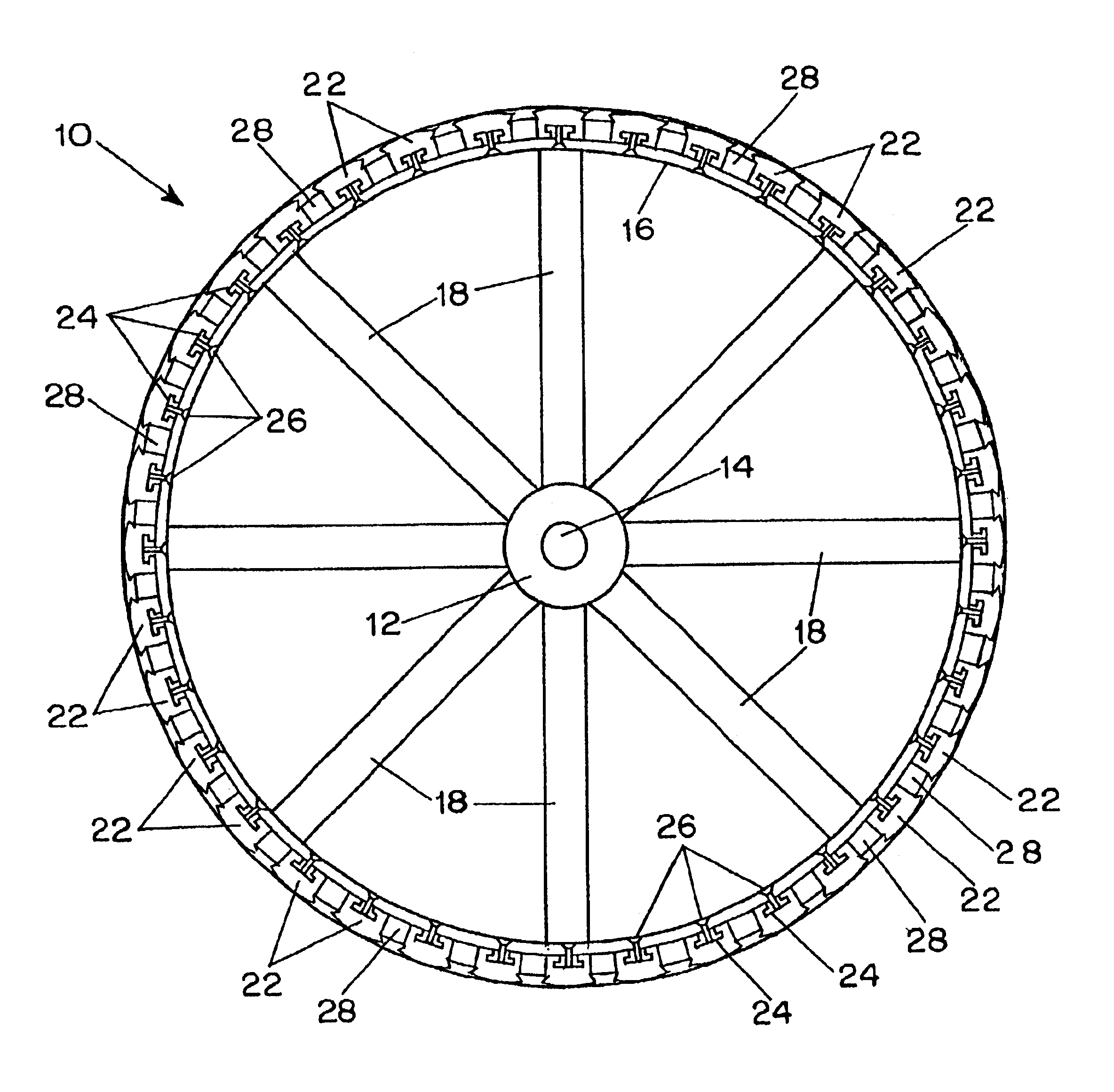
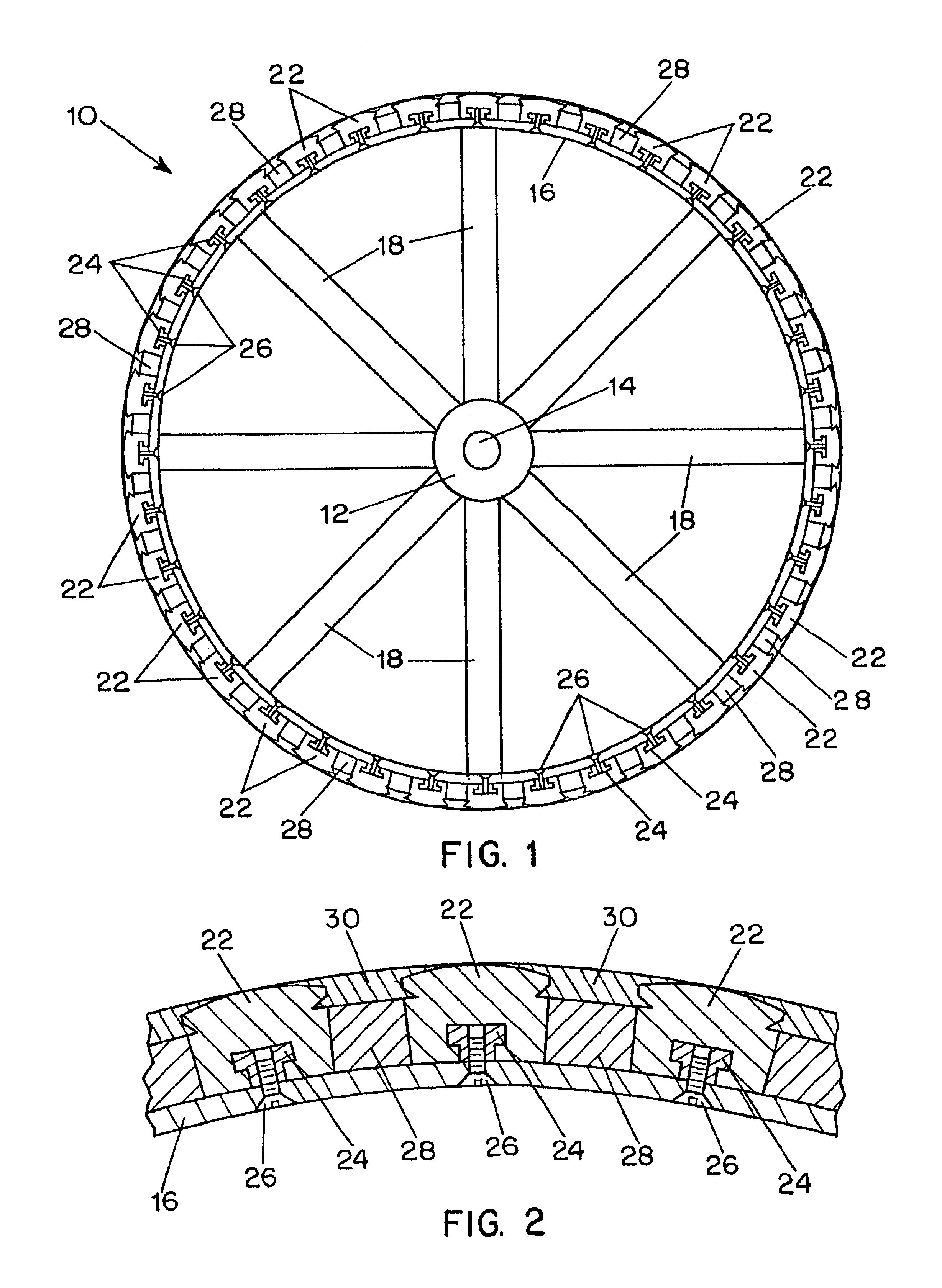
In the typical embodiment of the invention shown in FIGS. 1-3, a rotor 10 has a hub 12 supported on a shaft 14 and an inner ring 16 supported by spokes 18 from the hub 12. An array of magnetic pole pieces 22, circumferentially distributed around the periphery of the rotor, are affixed to the rotor inner ring 16 by pole retainers 24 held by removable seal members such as screws 26 extending through the inner ring 16.
Between each adjacent pair of pole pieces 22 a permanent magnet 28 is retained in place radially by a non-magnetic wedge member 30 having edges shaped to form an inter-locking engagement with the adjacent pole pieces 22 disposed on opposite sides of the magnet 28 and engaging the radially outer surface of the magnet.
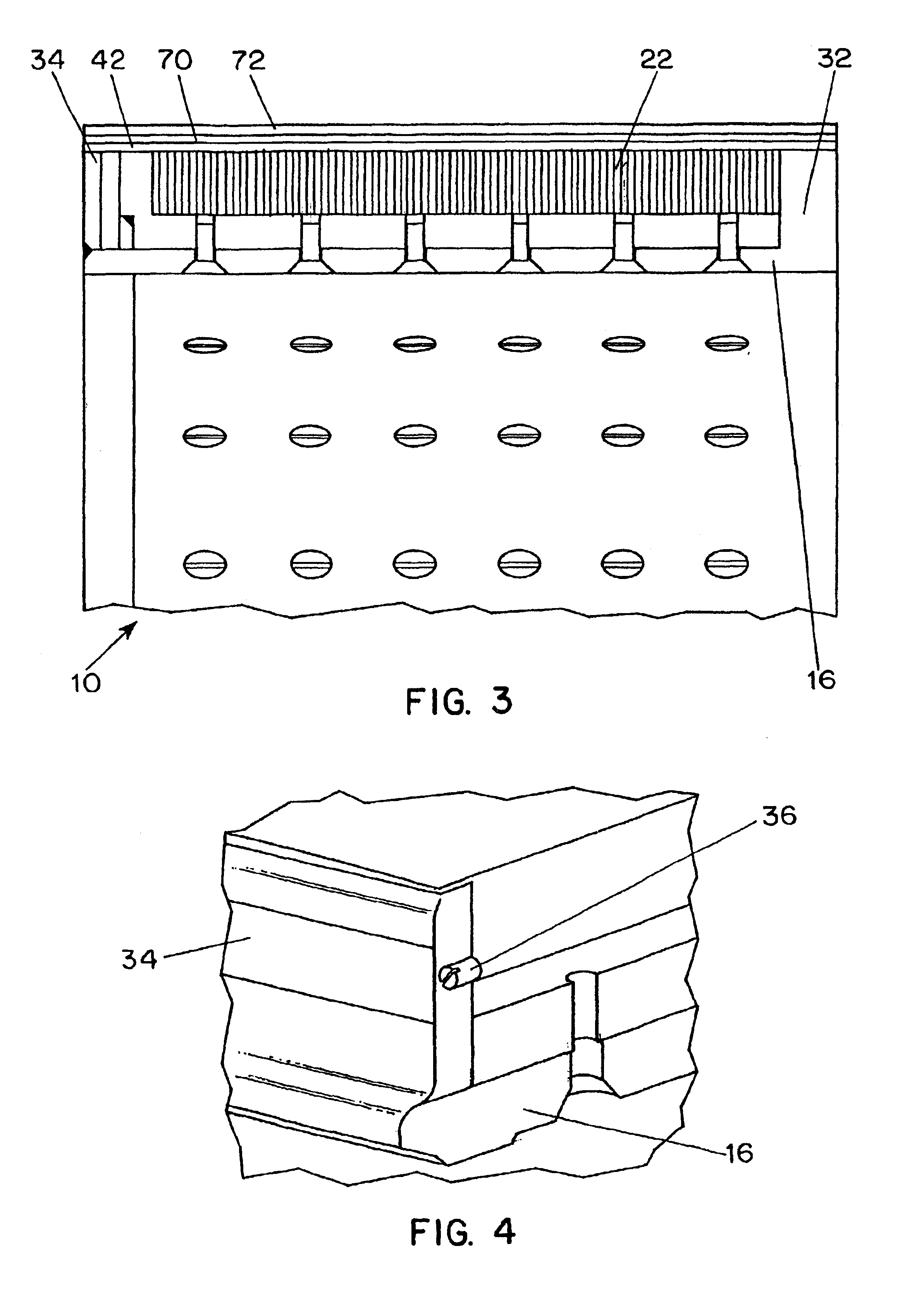
As shown in FIG. 3 the pole pieces 22 and magnets 28 are retained in the axial direction of the rotor at one end of the inner ring 16 by a shoulder 32 at one end and at the opposite ends by a rotor closure plate 34 welded to the rotor inner ring. As best seen ...
PUM
 Abstract
Description
Claims
Application Information
 - R&D
- Intellectual Property
- Life Sciences
- Materials
- Tech Scout
- Unparalleled Data Quality
- Higher Quality Content
- 60% Fewer Hallucinations
Browse by: Latest US Patents, China's latest patents, Technical Efficacy Thesaurus, Application Domain, Technology Topic, Popular Technical Reports.
© 2025 PatSnap. All rights reserved.Legal|Privacy policy|Modern Slavery Act Transparency Statement|Sitemap|About US| Contact US: help@patsnap.com


