Plasma display device with heat radiating plate

a technology of display device and heat radiating plate, which is applied in the direction of luminescnet screen, discharge tube, identification means, etc., can solve the problems of increasing transferring an external impact, and affecting the effect of the total weight of the pdp

Inactive Publication Date: 2005-01-25
LG ELECTRONICS INC
View PDF7 Cites 11 Cited by
  • Summary
  • Abstract
  • Description
  • Claims
  • Application Information

AI Technical Summary

Benefits of technology

Accordingly, it is an object of the present invention to provide a plasma display device that is adaptive for absorbing an external impact as well as reducing its weight.

Problems solved by technology

However, since a metal of aluminum material fails to absorb or alleviate an impact, it transfers an external impact to the panel as it is.
Accordingly, the panel 40 is liable to be damaged by an external impact.
Moreover, the aluminum metal has a heavy weight to cause an increase in total weight of the PDP.
If the PDP has an increased weight, then it has a limit in its installation place.
However, if the weight of the PDP is increased, then the PDP installed at a wall or ceiling may depart from the wall or ceiling to be damaged.
Particularly, when the wall or ceiling is made of a material having a weak strength such as wood, the PDP having a heavy weight is liable to depart from the wall or ceiling.

Method used


Image

  • Plasma display device with heat radiating plate
  • Plasma display device with heat radiating plate
  • Plasma display device with heat radiating plate

Examples


Embodiment Construction

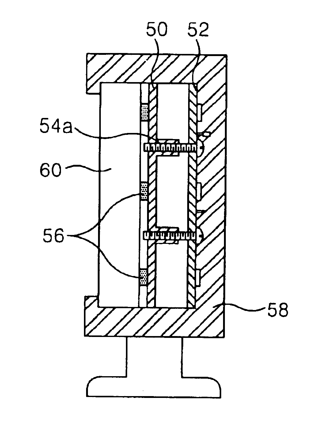
FIG. 4 and FIG. 5 shows a plasma display device and a heat-radiating plate according to an embodiment of the present invention.

Referring to FIG. 4 and FIG. 5, the plasma display device includes a panel 60, a heat-radiating plate 50, a driving circuit board 52 and a sash 58.

The panel 60 has a plurality of discharge cells arranged in a matrix type. The heat-radiating plate 50 is attached onto a non-display area of the panel 60.

The driving circuit board 52 is attached to the heat-radiating plate 50 to apply a desired driving signal to the panel 40. To this end, the driving circuit board 52 and the panel 60 are electrically connected to each other by mean of a flexible cable (or flexible printed circuit). The sash 58 is provided to enclose the side surface of the panel 60, the heat-radiating plate 50 and the driving circuit board 52, thereby protecting the driving circuit board 52 from an external impact.

The heat-radiating plate 60 is attached to a non-display area of the panel 60 by me...


PUM

PropertyMeasurementUnit
thermal crosslinkableaaaaaaaaaa
thermalaaaaaaaaaa
thermal conductivityaaaaaaaaaa

Abstract

A plasma display device that is adaptive for absorbing an external impact and reducing its weight. In the device, a heat-radiating plate is made from a polymer complex material that is a mixture of a resin with a metal material.

Description

BACKGROUND OF THE INVENTION1. Field of the InventionThis invention relates to a plasma display device, and more particularly to a plasma display device that is adaptive for absorbing an external impact as well as reducing its weight.2. Description of the Related ArtGenerally, a plasma display panel (PDP) is a display device utilizing a visible light emitted from a phosphor layer when an ultraviolet ray generated by a gas discharge excites the phosphor layer. The PDP has an advantage in that it has a thinner thickness and a lighter weight in comparison to the existent cathode ray tube (CRT) and is capable of realizing a high resolution and a large-scale screen. The PDP includes a plurality of discharge cells arranged in a matrix pattern, each of which makes one pixel of a field.FIG. 1 is a perspective view showing a discharge cell structure of a conventional three-electrode, alternating current (AC) surface-discharge PDP.Referring to FIG. 1, a discharge cell of the conventional three...

Claims


Application Information

Patent Timeline
Patent Type & Authority Patents(United States)
IPC IPC(8): G09F9/313H01J17/49
CPCG09F9/313H01J2217/49H01J11/20H01J17/28
Inventor KIM, SOON HAK
Owner LG ELECTRONICS INC
Why Eureka
Try Eureka