Lens actuator

a technology of actuators and actuators, applied in the field of lenses actuators, can solve the problems of increasing production costs, reducing yields, and reducing torsional rigidity in a radial direction, so as to reduce the influence of roll resonance factor, prevent over attenuation, and improve speed

Inactive Publication Date: 2005-01-25
RICOH KK
View PDF2 Cites 51 Cited by
  • Summary
  • Abstract
  • Description
  • Claims
  • Application Information

AI Technical Summary

Benefits of technology

According to the present invention, by using the damper having characteristics of obtaining the maximum attenuation or the maximum loss in a vicinity of the resonance frequency around the tangential axis in the objective lens actuator, it is possible to prevent over attenuation in an active resonance frequency and alto it is possible to reduce influence of the roll resonance factor detrimental to improvement in the speed.
Alternatively, by using a damper having characteristics of obtaining a maximum attenuation or a maximum loss in a vicinity of an usable maximum rotation frequency of the optical recording and reproducing apparatus, it is possible to prevent the over attenuation in the active resonance frequency and it is possible to suppress the influence of the roll resonance factor detrimental to improvement in the speed.
Moreover, alternatively,

Problems solved by technology

In addition, since an outside dimension is limited by minimization and be lightweight and an arrangement and a size of the support spring are limited, there is a problem such that a torsional rigidity in a radial direction is inevitably degraded due to a principal of this mechanism.
The irregular rotational motion in the radial direction is caused during the translational motion, by an assembly error, by an irregular moment of a driving thrust when a focusing operation and a tracking operation are translationally shifted, or by a slight asymmetry caused by an assembly error of a support spring.
The occurrence of the irregular rotational motion causes characteristic problems and also decreases a yield and increases costs of production.
However, when the translational thrust is occurred to each of the focusing operation and the tracking operation, it is not possible to prevent a state in which the DC shift occurs in the tracking direction and the focusing direction that are perpendicular each other.
A tilt amount in the radial direction by AC (Alternating Current) caused by the rotation resonance exceeds far above a peak value of a tilt amount in the radial direction conventionally caused by the DC shift, and modulates an amplitude of a tracking error signal or a RF (Radio Frequency) signal and then prevents a stable performance of recording or reading.
Thus, a servo error can occur.
Since these above problems are related to the resonance, it is not effective to use a means of offsetting irregular moments of the focusing operation and the tracking operation, which are used for an irregular inclination in a consideration of the DC shift only.
When the surface vibration of the optical disk or the AC exciting force for an eccentric follow-up additionally occurs in an inevita

Method used


Image

  • Lens actuator
  • Lens actuator
  • Lens actuator

Examples


first embodiment

[First Embodiment]

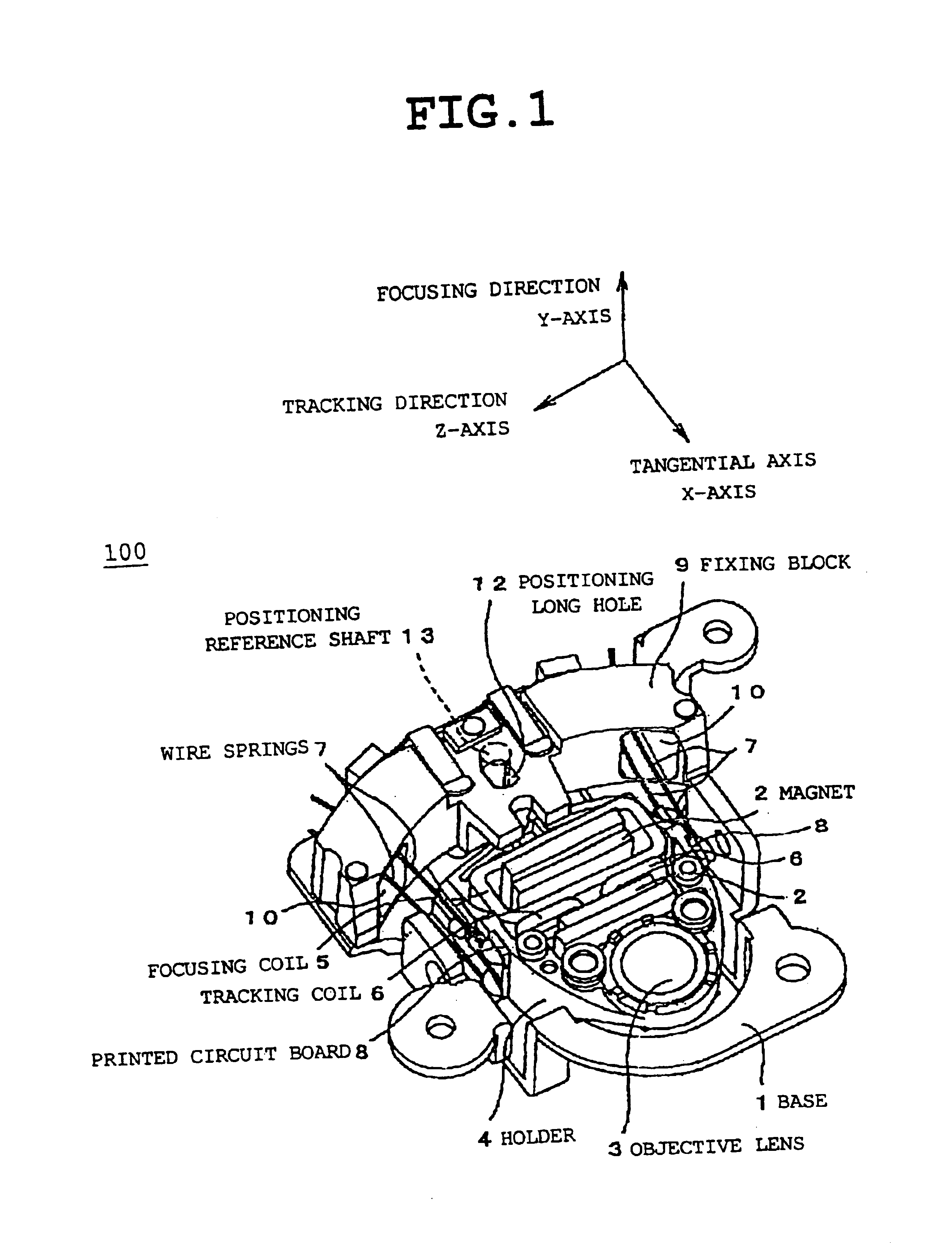
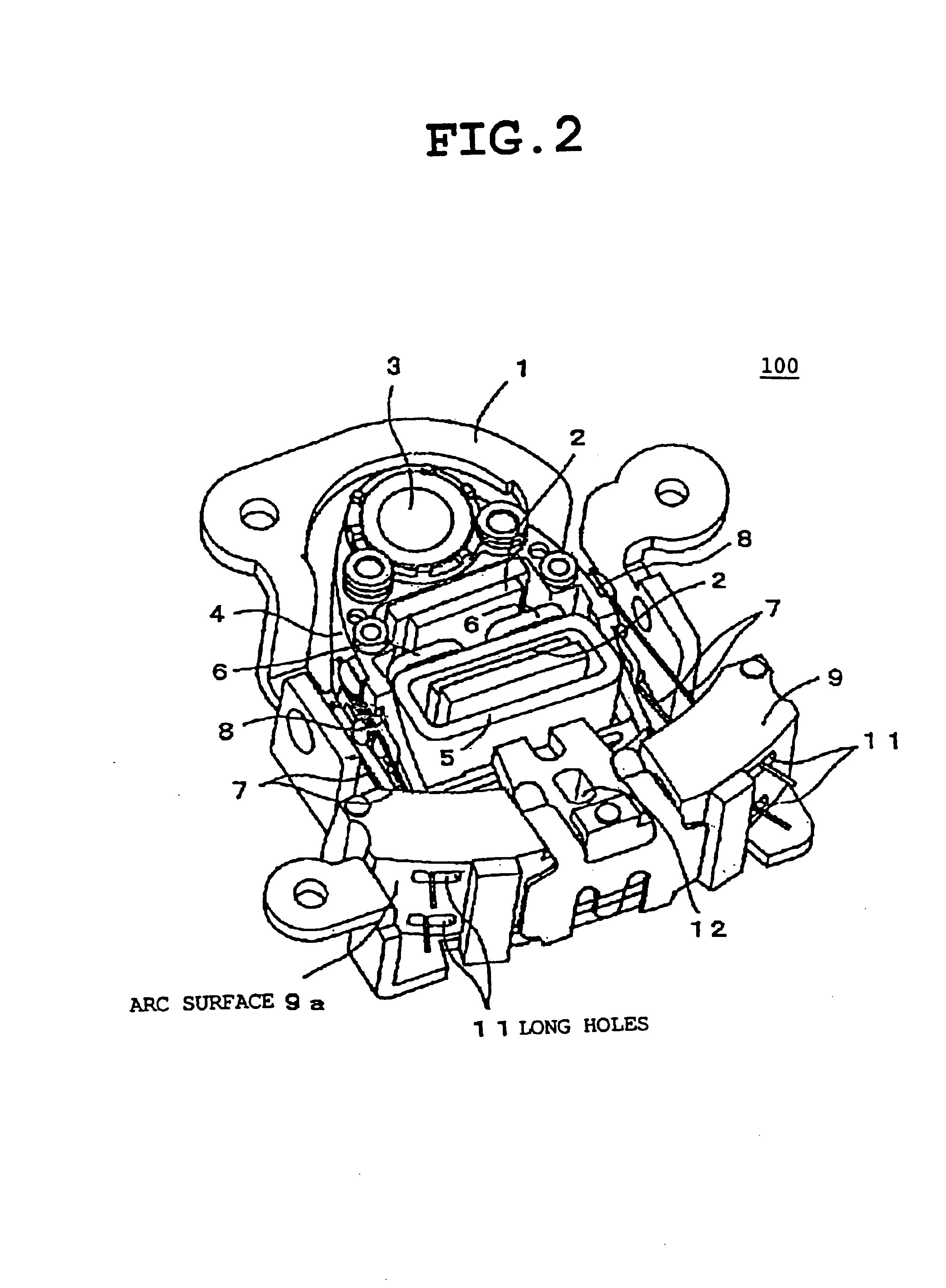
FIG. 1 is a perspective diagram showing a front side of a lens actuator according to an first embodiment of the present invention. FIG. 2 is a perspective diagram showing a back side of the lens actuator in FIG. 1. The lens actuator 100 includes a base 1, a magnet 2 provided so as to face to the base 1, an objective lens 3, a holder 4 holding the objective lens 3, a focusing coil 5, a tracking coil 6, at least four wire springs 7 that are holder support springs, a printed circuit board 8 for fixing the wire springs 7 fixed at both sides of the holder 4 and for a coil electric supply, and a fixing block 9 for fixing ends of the wire springs 7.

A movable part includes the objective lens 3 fixed to and held by the holder 4, the focusing coil 5, the tracking coil 6, and the printed circuit board 8. A fixing part includes the base 1 serving as a back yoke of a magnetic circuit, the magnet 2, the fixing block 9 fixed on the base 1.

A fixed magnetic circuit is formed by the...

second embodiment

[Second Embodiment]

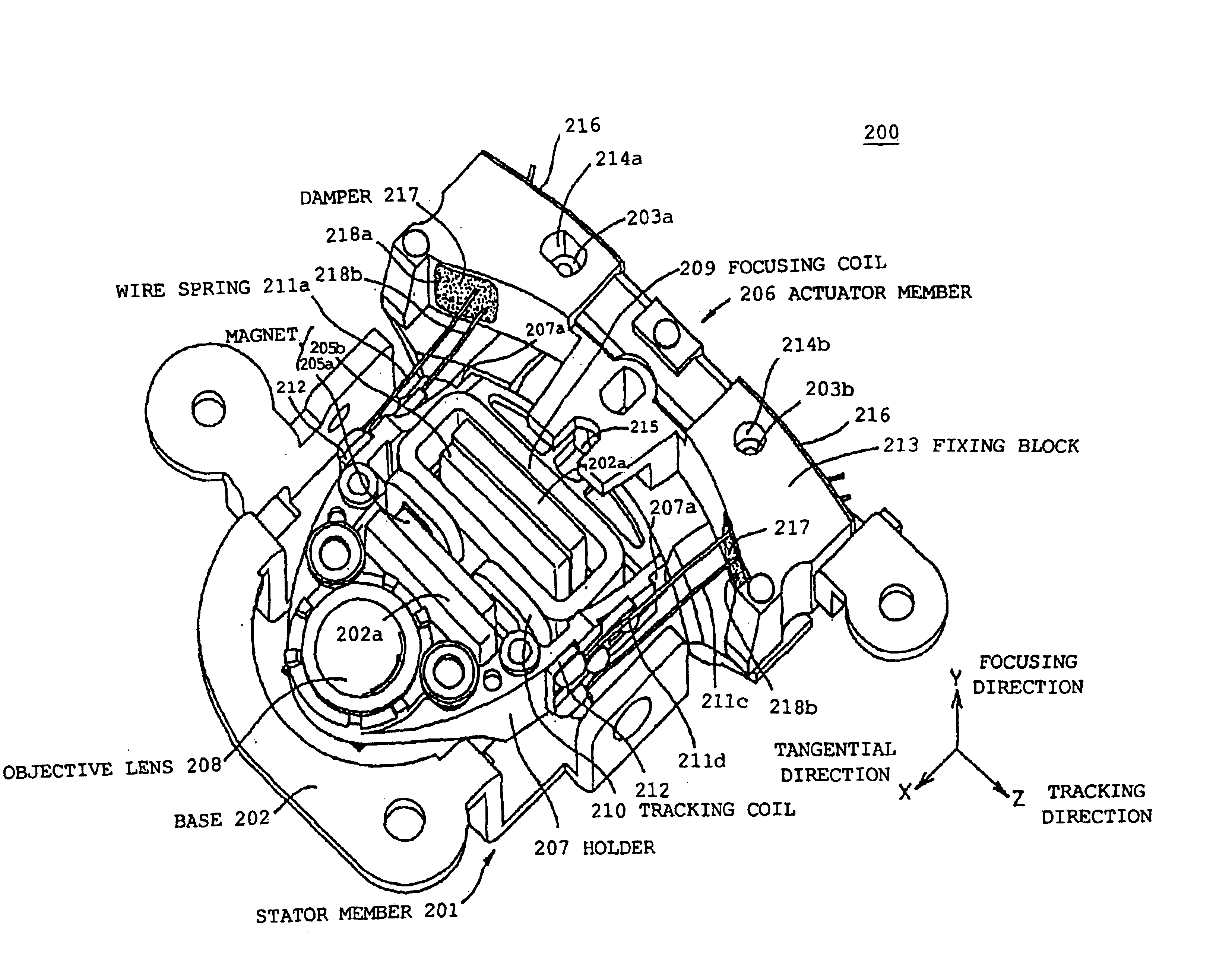
FIG. 9 is a perspective diagram showing the lens actuator assembly according to a second embodiment of the present invention. FIG. 10 is a perspective diagram showing a stator member containing a fixed magnetic circuit after decomposing the lens actuator assembly of FIG. 9. FIG. 11 is a perspective diagram showing an actuator part containing a movable part and a support structure after decomposing the lens actuator assembly of FIG. 9. In FIG. 9, a X-axis direction is a focusing direction and a Z-axis direction is a tracking direction (radial direction).

In FIG. 9 and FIG. 10, a lens actuator 200 includes a stator member 201, a base 202, bosses 203a and 203b, magnets 205a and 205b, and a standing wall 202a for fixing the magnets 205a and 205b on the base 202. The standing wall 202a also serves as a back yoke.

In addition, in FIG. 9 and FIG. 11, the lens actuator 200 includes an actuator part 206, a holder 207, an objective lens 208, a focusing coil 209, a tracking co...


PUM


Abstract

In a lens actuator for use with an optical recording and reproducing apparatus in accordance with a plurality of different multiplied response numeric values to record or reproduce to or from an optical recording medium, the lens actuator actuates an objective lens to control focusing and tracking and includes a fixed magnetic circuit including a magnet as a magnetic flux generating source and a back yoke, a support structure that is elastically displaceable depending on a thrust generated amount; and a movable part including a holder fixing the objective lens and a solenoid coil capable of generating a focusing thrust and a tracking thrust in accordance with current values, respectively. And in the lens actuator, a resonance frequency around a tangential axis is set to be different from spindle rotation frequencies corresponding to the plurality of multiplied response numeric values.

Description

BACKGROUND OF THE INVENTION1. Field of the InventionThe present invention generally relates to a lens actuator used for a device (hereinafter called an optical disk drive device) including a plurality of values for different multiplied speeds for optically recording and reading information to a recording medium.2. Description of the Related ArtIn a lens actuator used for an active control, it is required to employ a movement mechanism for maximally reducing a loss operation caused by a non-linear characteristic. Thus, a spring support mechanism has been widely applied as a support mechanism of the lens actuator used in the optical disk drive device that requires a high accurate control. A detailed description of a mechanism supporting a light pickup by four support springs (linier elastic member) is found in Japanese Laid-Open Patent Application No.9-190636 (Japanese Patent No.2856176), for example.On the other hand, since it is required to mount a high NA objective lens due to an i...

Claims


Application Information

Patent Timeline
IPC IPC(8): G11B7/09
CPCG11B7/0932
Inventor TANAKA, AKIHIRO
Owner RICOH KK
Why Eureka
Try Eureka