Servo with digital filter to control gain in a frequency band where open loop characteristic is higher than the phase cross-over frequency and lower than resonance frequency

a technology of digital filter and servo, which is applied in the direction of instruments, disposition/mounting of heads, and maintaining head carrier alignment, etc., can solve the problems of frequency delay, insufficient increase of control band, and difficulty in implementing these two requirements, so as to maintain stability and improve control band

Inactive Publication Date: 2005-01-25
FUJITSU LTD
View PDF14 Cites 12 Cited by
  • Summary
  • Abstract
  • Description
  • Claims
  • Application Information

AI Technical Summary

Benefits of technology

With the foregoing in view, it is an object of the present invention to provide a storage device, tracking control method, and a tracking control unit for making the control band wide with a sufficient phase margin at the high frequency area, without increasing the sampling frequency.
According to the present invention, in a frequency area between a phase cross-over frequency f6 of the open loop characteristic of the servo control system and the resonance frequency f9 of the carriage, gain is increased to a position which is higher than the gain margin at f6 within a range where gain does not become OdB or more at a point where the phase becomes (−180+360×N)° wherein, N=0, +−1, +−2 . . . . So, phase at the gain cross-over frequency is advanced, and the control band is improved.
Also according to the present invention, a feedback control unit is configured using a digital filter, which has a secondary pole to make the attenuation coefficient 1 or less, in an area between the phase cross-over frequencies f6 and f9 and in a frequency area where the phase of the open loop transfer function is −540° or more and −180° or less, and where the gain of the open loop transfer function at the frequency of the pole is increased to a position which is higher than the open loop gain at frequency f6. So phase at the gain cross-over frequency is advanced while maintaining stability equivalent to a conventional control unit, and the control band is improved.
Also according to the present invention, the gain of the open loop transfer function at the frequency of the pole of the digital filter is increased to a position higher than OdB, so that the phase at the gain cross-over frequency is advanced while maintaining stability equivalent to a conventional control unit, and the control band is improved.
Therefore when gain is intentionally raised by the digital filter, as in the feedback control unit of the present invention, phase can be advanced by the rise of gain while sufficiently maintaining stability, and the control band can be improved as a result.

Problems solved by technology

It is difficult to implement these two requirements with the configuration of a general feedback controller.
Because if a gain at a high frequency area is decreased to maintain robust stability against higher resonance, a phase near gain cross-over frequency delays, and the control band cannot be sufficiently increased.
The phase delay due to this delay time is also a cause which makes an increase in the control band difficult.
In other words, in the case of the above mentioned actuator which can control driving for both precision and coarse control, generally it is difficult to increase higher resonance frequency, so a gain of tracking control cannot be increased (gain cross-over frequency cannot be increased), and it is hard to support high-speed disk rotation.
However, if a twin T filter where the dip frequency is low (close to the gain cross-over frequency) is inserted into the loop to be controlled, a large phase delay is generated at the gain cross-over frequency by the twin T filter, and phase margin decreases.
However, an actuator generally has a plurality of resonance modes, so it is very difficult to correctly measure a higher resonance frequency to be the problem, from the response to the applied signal, as was proposed above.
When a narrow band notch filter is used, in particular, the attenuation characteristic differs greatly when there is a slight frequency change, so an error in measurement leads to the deterioration of servo characteristics and it is difficult to completely eliminate the influence of higher resonance.
Also, to measure a higher resonance frequency, expensive hardware or complicated software are required separately, which increases cost.
Keeping the sampling frequency low, in particular, increases the dead time of a digital filter, and makes the phase conditions of the control system strict, which make band improvement difficult.
Therefore, it is required a high-speed digital circuit, such as high-speed DSP, and cost is increased.

Method used


Image

  • Servo with digital filter to control gain in a frequency band where open loop characteristic is higher than the phase cross-over frequency and lower than resonance frequency
  • Servo with digital filter to control gain in a frequency band where open loop characteristic is higher than the phase cross-over frequency and lower than resonance frequency
  • Servo with digital filter to control gain in a frequency band where open loop characteristic is higher than the phase cross-over frequency and lower than resonance frequency

Examples


Embodiment Construction

Embodiments of the present invention will now be described in the sequence of a tracking control system, a digital filter, and other embodiments, with reference to the accompanying drawings.

Tracking Control System

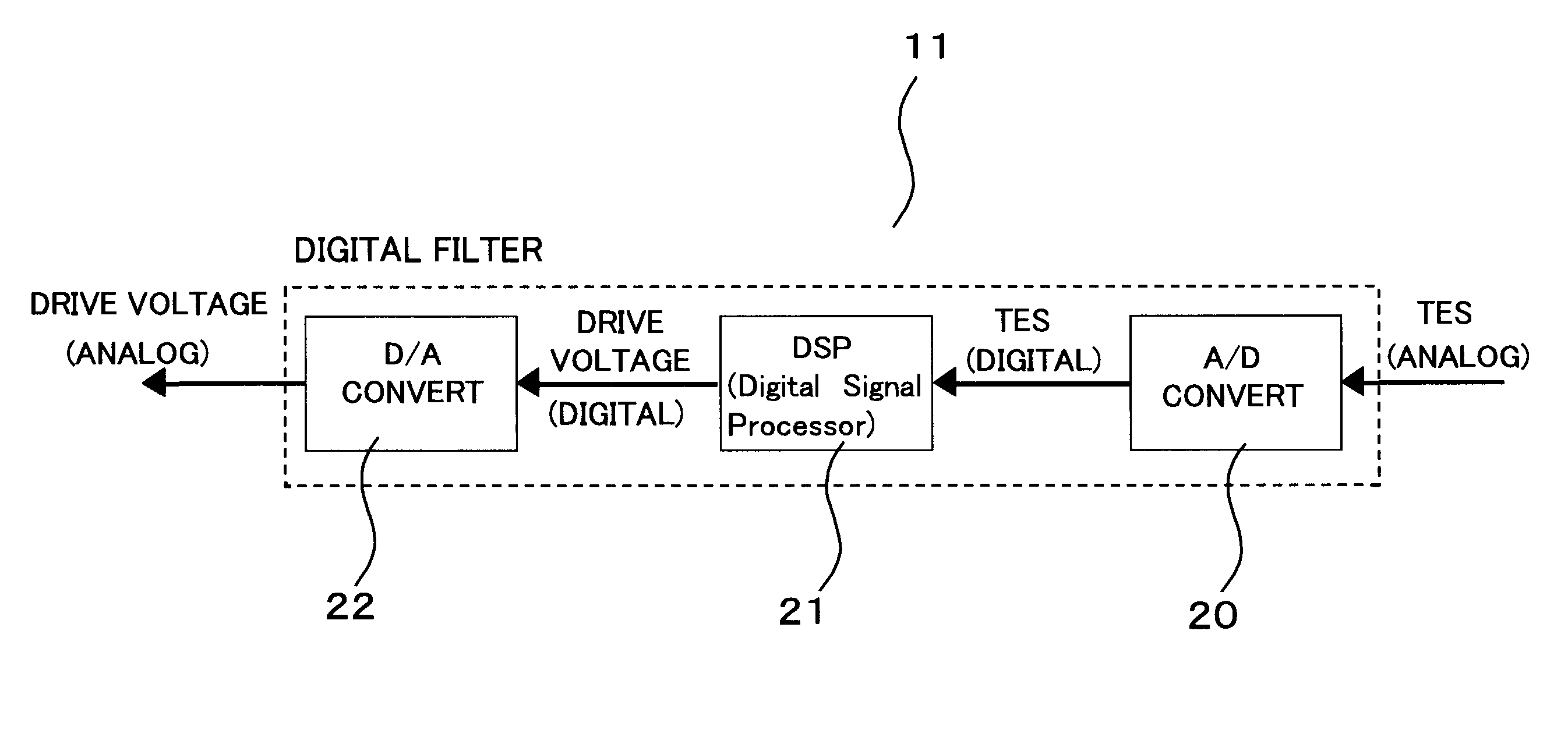
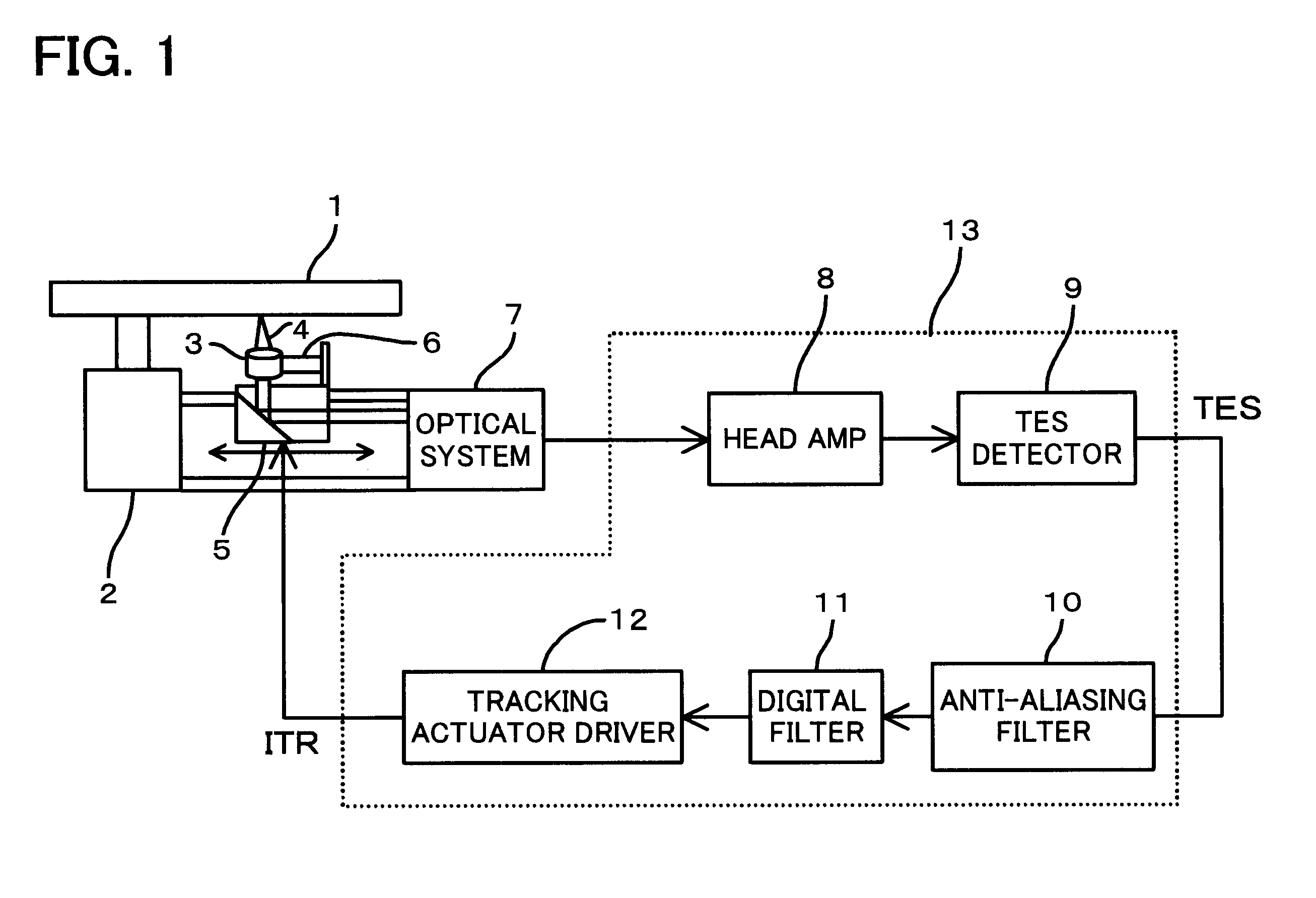
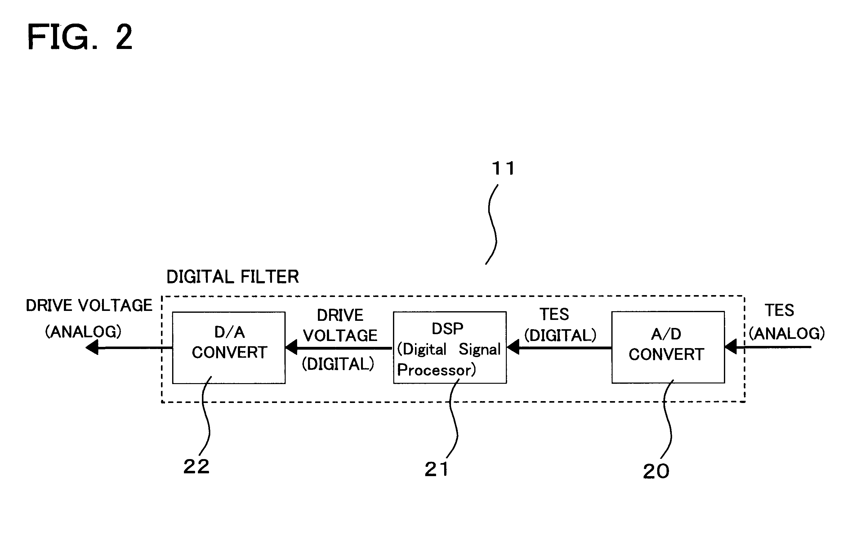
FIG. 1 is a block diagram depicting the configuration of the tracking control system of the optical disk unit according to an embodiment of the present invention, and FIG. 2 is a block diagram of the servo control unit (digital filter) thereof. Here, the parts which are not directly related to the description of the present embodiment, such as a reproducing signal processing circuit, an interface circuit with the host computer, and a focus control circuit, are omitted.

As FIG. 1 shows, the optical disk unit, where an optical disk 1 having information tracks to record information is set, has a spindle motor 2 which rotates to drive the optical disk 1. In the optical disk unit, the optical head for recording and reproducing information to / from the optical disk 1 is comprised o...


PUM

PropertyMeasurementUnit
frequency f9aaaaaaaaaa
frequencyaaaaaaaaaa
frequencyaaaaaaaaaa

Abstract

The present invention implements a servo system which can support changes of the higher resonance frequencies of the actuator with a simple configuration at low cost. The servo system comprises a head 3 which at least reads a disk 1, a carriage 5 which drives the head 3 to the track position of the disk 1, a detection circuit 9 which detects a positional error with respect to the track from the read output of the head, and the servo control unit 11 which controls the carriage such that the head follows up the track according to the positional error, wherein the servo control unit 11 further comprises a digital filter for increasing gain so that the open loop characteristic of the tracking servo system by the servo control unit has a gain higher than the open loop gain of the phase cross-over frequency f6 in a frequency area which is higher than the phase cross-over frequency f6 but lower than the higher resonance frequency f9 of the carriage and where the gain does not becomes OdB or more at a frequency where phase is (−180+360×N)°. Since gain is increased, phase margin is increased.

Description

BACKGROUND OF THE INVENTION1. Field of the InventionThe present invention relates to a storage device which reproduces / records information from / to a storage medium, a tracking control method, and a tracking control unit thereof.2. Description of the Related ArtIn a storage device such as an optical disk unit and a magnetic disk unit, a tracking control method is used where a relative position between a read head and a target track is detected and the signal is input to a head drive unit via an analog or digital controller, so that the head follows up the positional changes of the track.As the price of storage device comes down, decreasing the number of components and the number of manufacturing steps is demanded for the disk unit. For this, a precision / coarse integrated type drive unit, where a precision actuator and a coarse actuator are not separated, is often used to configure a head drive unit.For example, in order to implement low cost in the tracking control system of an optic...

Claims


Application Information

Patent Timeline
Patent Type & Authority Patents(United States)
IPC IPC(8): G11B7/09G11B5/596G11B7/085G11B7/095
CPCG11B5/59622G11B7/0941G11B7/0953G11B7/08517
Inventor IKAI, YOSHIAKI
Owner FUJITSU LTD
Why Eureka
Try Eureka