Shuffling device, coding device, decoding device of video signal and medium recording the programs of shuffling, coding and decoding

a technology of coding device and video signal, which is applied in the direction of signal generator with optical-mechanical scanning, color television with bandwidth reduction, etc., can solve the problems of complex structure of coding device, inability to efficiently use code-quantity allotted to the segment, etc., and achieves simple structure, reduce overflow, and improve picture quality

Inactive Publication Date: 2005-01-25
GK BRIDGE 1
View PDF13 Cites 35 Cited by
  • Summary
  • Abstract
  • Description
  • Claims
  • Application Information

AI Technical Summary

Benefits of technology

Another object of the present invention is to provide a coding device of a video signal and a recording medium including the coding program. The coding device efficiently uses a code-quantity allotted to a segment, improves picture quality and reduces overflows.
Still anther object of the present invention is to provide another coding device of a video signal and a re

Problems solved by technology

As a result, correlations between data within a segment become loose, thereby preventing the data lengths in respective segments from being dispersed.
Thus the code-quantity produced in the segment becomes so less than a target code-quantity that

Method used


Image

  • Shuffling device, coding device, decoding device of video signal and medium recording the programs of shuffling, coding and decoding
  • Shuffling device, coding device, decoding device of video signal and medium recording the programs of shuffling, coding and decoding
  • Shuffling device, coding device, decoding device of video signal and medium recording the programs of shuffling, coding and decoding

Examples


exemplary embodiment 1

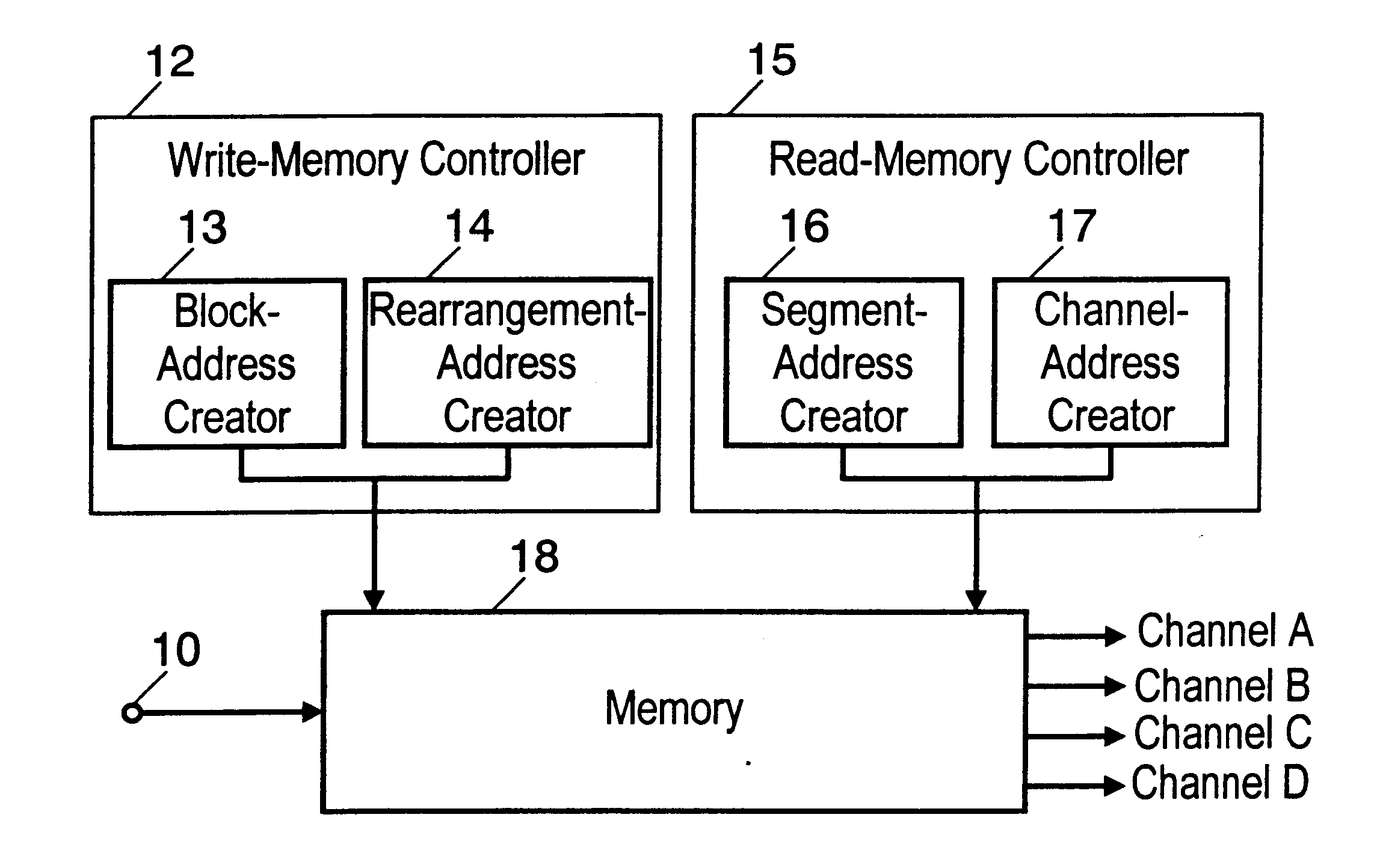
FIG. 1 is a block diagram of a video signal shuffling device in accordance with the first exemplary embodiment of the present invention.

In FIG. 1, a digital video signal received at input terminal 10 is fed into memory 18.

Block-address creator 13 creates addresses for the blocks divided from an input data. Rearrangement-address creator 14 creates addresses for the blocks rearranged in a memory.

Write-Memory controller 12 calculates an address in the memory unique to the input data on the screen through block-address creator 13 and rearrangement-address creator 14, and controls the input data to be written into the unique address in the memory.

Read-Memory controller 15 reads the data from the memory through segment-address-creator 16 and channel-address-creator 17, and outputs the data to a given channel. Segment-address-creator 16 creates a segment based on the data in memory 18, and channel-address-creator 17 creates an address for outputting the segment.

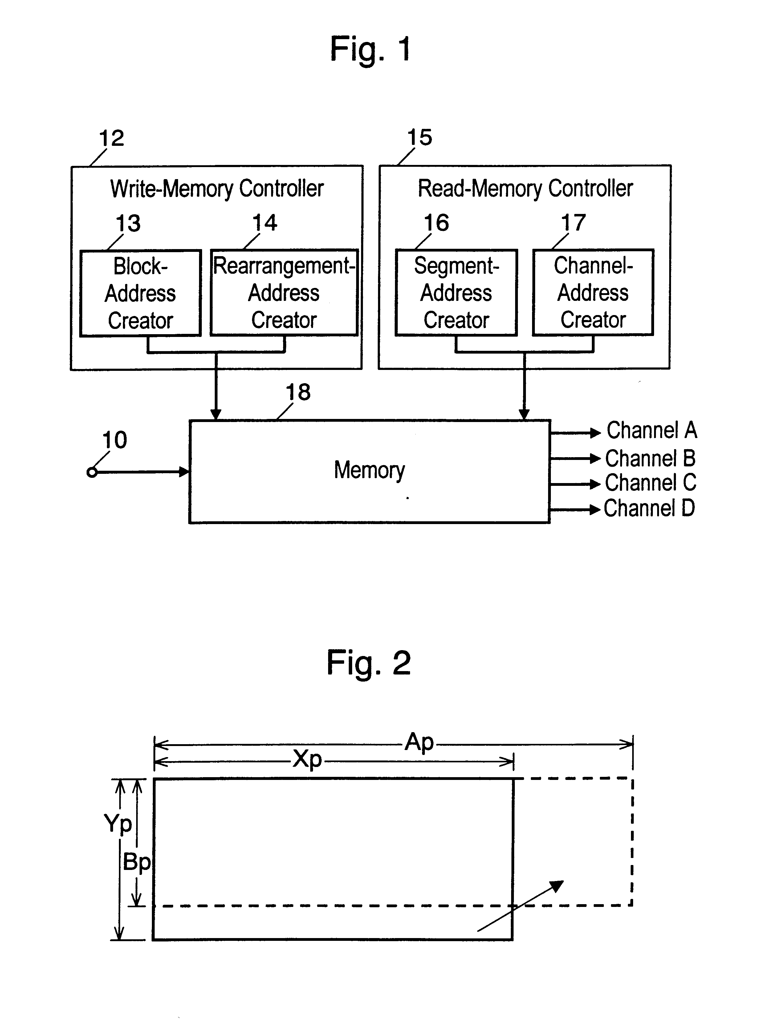
FIG. 2 illustrates how to wr...

exemplary embodiment 2

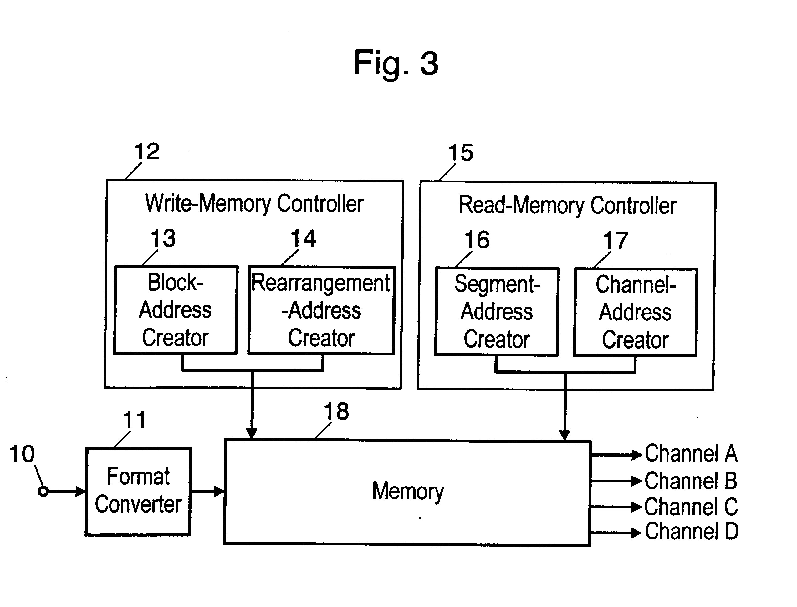
FIG. 3 is a block diagram of a video signal shuffling device in accordance with the second exemplary embodiment of the present invention.

In FIG. 3, a video signal received at input terminal 10 is fed into format converter 11.

Format converter 11 limits the bandwidth and converts a number of pixels of the input signal.

Assume that the input signal is formed of Mp (the number of H pixels) and Np (the number of V lines). Mp and Np have the following relations with an input signal of Xp (H) and Yp (V): Mp>=Xp, Np>=Yp.

Format converter 11 then reduces a number of pixels to convert the input signal into a form of Xp (H)×Yp (V) before supplying the signal to memory 18.

The video-signal-shuffling device discussed above in accordance with the second embodiment can be formed by (a) adding the format converter to the device used in the first embodiment and (b) forming the input signal into a format agreeing with a shuffling pattern. As a result, this shuffling device can deal with signals of vario...

exemplary embodiment 3

FIG. 4 illustrates the shuffling in accordance with the third exemplary embodiment of the present invention.

The structure of the shuffling device used in this embodiment is the same as shown in FIG. 3. An operation of this shuffling device is demonstrated with reference to FIGS. 3 and 4.

A video signal of the following characteristics (refer to FIG. 4(a)) is fed into terminal 10.a number of effective lines: 1080;a number of effective pixels in horizontal direction of a luminance signal (signal Y): 1920 / line; andnumbers of effective pixels in horizontal direction of two color-differential signals (signal Cr and signal Cb): 960 each

Format converter 11 limits the bandwidth of input signal and converts the input signal into the following format (refer to FIG. 4(b)):a number of pixels in horizontal direction of signal Y: 1280; andnumbers of pixels in horizontal direction of signals Cr and Cb: 640 each.

Regarding region 1 occupying 1072 lines out of 1080 effective lines, block-address creat...


PUM


Abstract

A video signal shuffling device forms a segment with blocks having a given offset value in horizontal and vertical directions from a given starting point uniquely determined on the screen, the offset value being identical in every region. The segment is formed in a unit of one frame or two frames. The shuffling device divides one frame comprising blocks into a plurality of regions. A coding device determines a final priority as well as a final quantizer thereby quantizing a segment and providing the segment with a variable-length-coding based on a first priority, coding-quantity obtained from a plurality of quantizers, second priority and a quantizer. A coding device and its decoder, the coding device carries out a hierarchical coding by only a motion vector in a compressed stream at a lower resolution side and by agreeing a motion detected and a DCT block size with a size on the screen.

Description

FIELD OF THE INVENTIONThe present invention relates to a shuffling device, coding device and decoding device of video signals as well as a medium recording the programs of shuffling, coding and decoding. More particularly, the present invention relates to the following subjects:(1) a shuffling device relating to television (TV) signals in the formats of high-definition TV (HDTV) and progressive method, and a medium recording the program of the shuffling(2) a coding device relating to controlling a quantity of codes generated in a segment, and a medium recording the program of the coding(3) a coding device and an decoding device relating to hierarchical coding in a direction of spatial coordinates standardized by Motion Picture Experts Group (MPEG).BACKGROUND OF THE INVENTIONRegarding the first subject, a shuffling method is one of high-efficient-coding methods for recording standard TV (SDTV) signals into a compressed-digital type video-cassette-recorder (VCR). This shuffling method...

Claims


Application Information

Patent Timeline
IPC IPC(8): H04N7/30H04N7/24
CPCH04N19/139H04N19/176H04N19/172H04N19/15H04N19/33H04N19/124H04N19/186H04N19/44H04N19/61
Inventor FUJIWARA, YUJINISHINO, MASAKAZUMIYASHITA, MITSUHIROWAKE, KAZUHIROTAKEUCHI, SEIICHIOKAMOTO, KEISHI
Owner GK BRIDGE 1
Why Eureka
Try Eureka