Device and method for package warp compensation in an integrated heat spreader

a technology of heat generation and dissipation device and heat spreader, which is applied in the direction of program control, instruments, error detection/correction, etc., can solve the problems of heat generation and dissipation, the size of components has become a more critical factor, and the time remains

Inactive Publication Date: 2005-02-01
INTEL CORP
View PDF3 Cites 40 Cited by
  • Summary
  • Abstract
  • Description
  • Claims
  • Application Information

AI Technical Summary

Benefits of technology

The benefits resulting from the present invention is that an IHS 10 may be designed that will create an approximately flat package even after manipulation and exposure to fluctuations in temperature. With such a near flat package it is possible to effectively and uniformly dissipate heat from a die. In addition, it is possible to increase the heat dissipation capacity of the IHS 10 for specific locations associated with hotspots in a die 50.

Problems solved by technology

However, with the increase in speed, reduction in the size of components, and increased density of circuitry found within a given chip / die, heat generation and dissipation have become a more critical factor than ever.
However, because the assembled package contains materials with different coefficients of thermal expansion, and because the package is assembled in steps at various temperatures and because temperature gradients exist in a “powered-up” package the IHS will deform so that it no longer remains flat.
Once this deformation occurs in the IHS, the thickness of the thermal interface material between the heat sink and the IHS would vary and the IHS would no longer be able to uniformly dissipate heat from the die to the heat sink.
Further, even though a die may be relatively small, the heat generated by a die may not be evenly distributed throughout the die.

Method used


Image

  • Device and method for package warp compensation in an integrated heat spreader
  • Device and method for package warp compensation in an integrated heat spreader
  • Device and method for package warp compensation in an integrated heat spreader

Examples


Embodiment Construction

Before beginning a detailed description of the subject invention, mention of the following is in order. When appropriate, like reference numerals and characters may be used to designate identical, corresponding or similar components in differing figure drawings. Further, in the detailed description to follow, exemplary sizes / models / values / ranges may be given, although the present invention is not limited to the same. As a final note, well-known components of computer networks may not be shown within the FIGs. for simplicity of illustration and discussion, and so as not to obscure the invention.

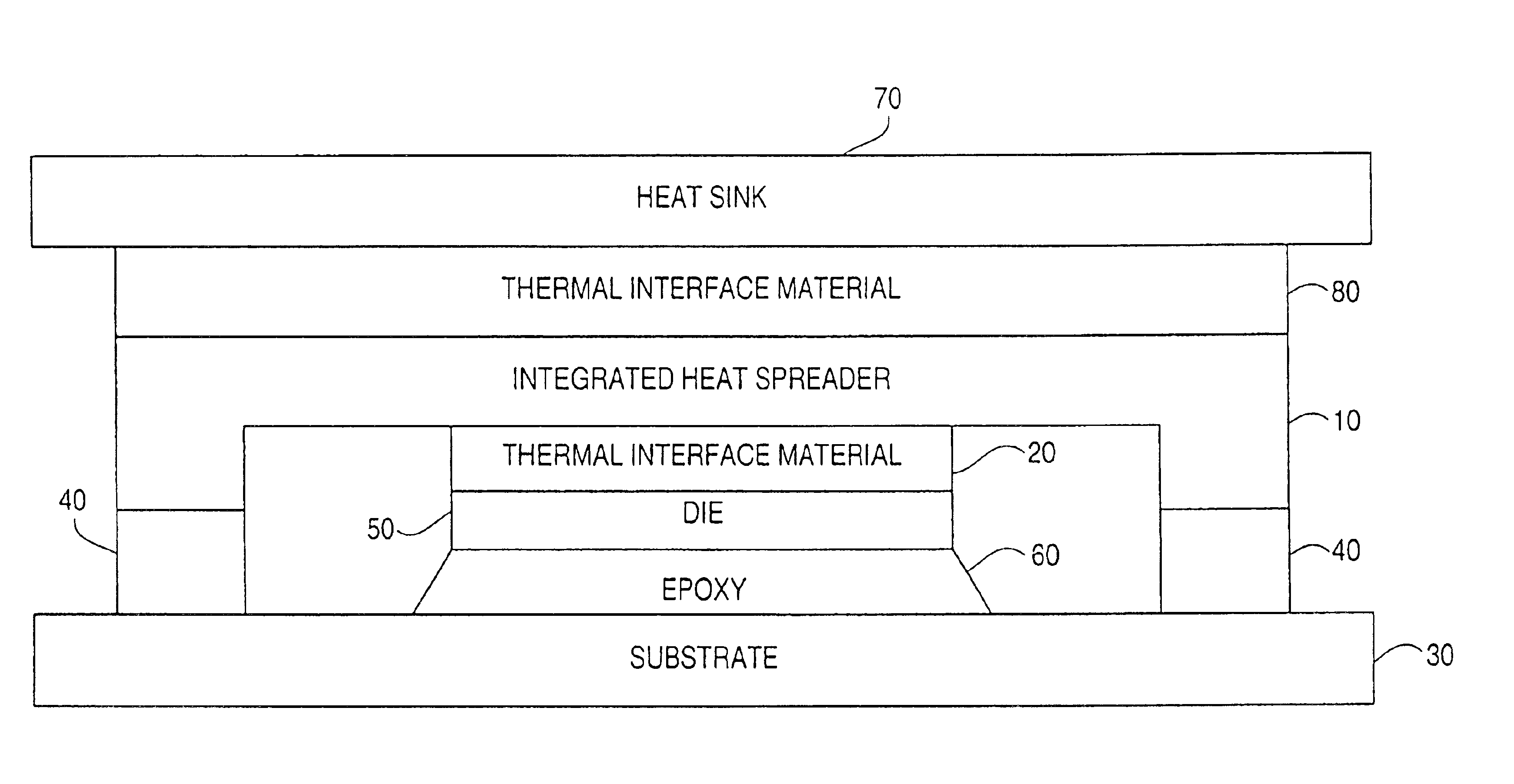
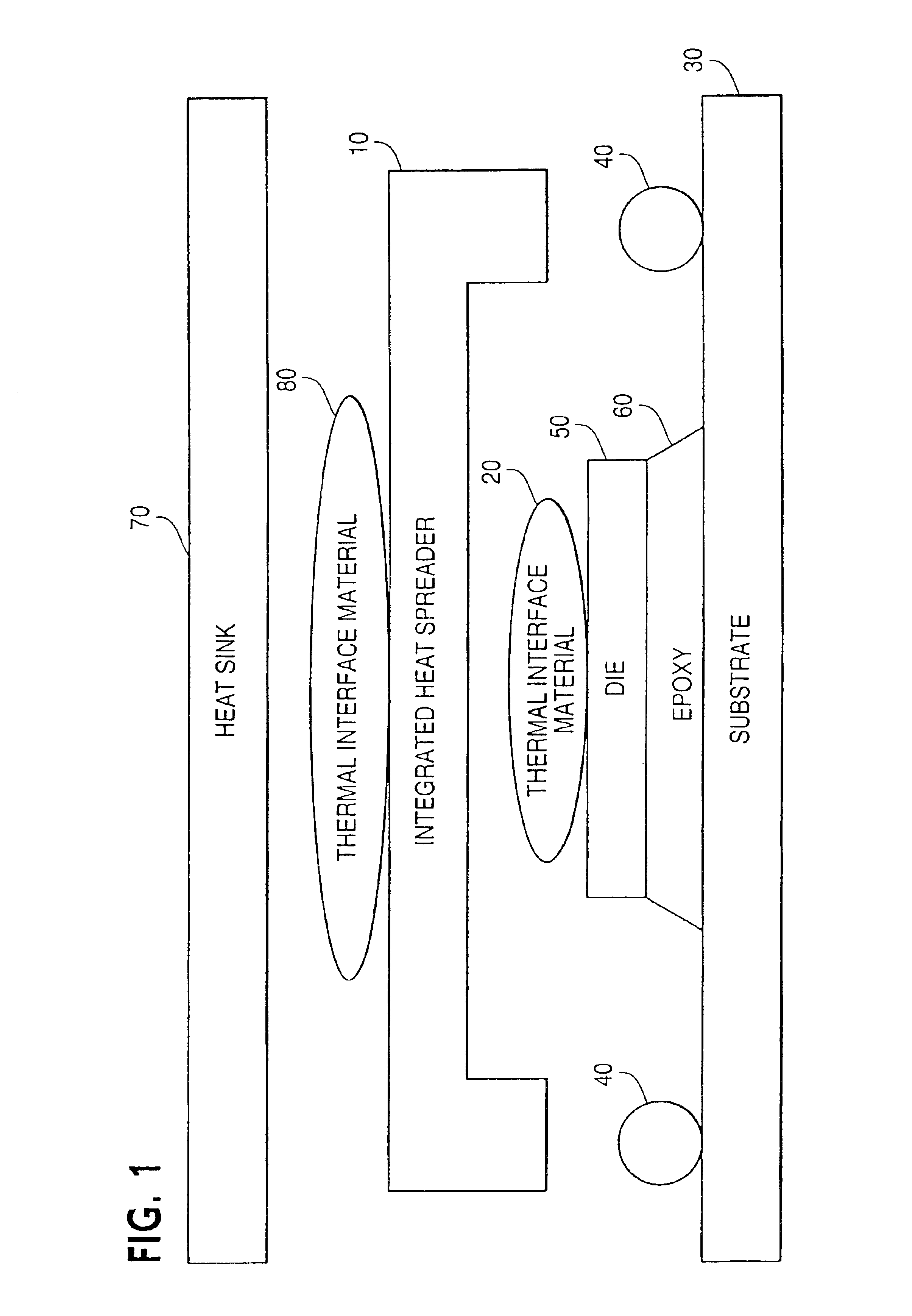
FIG. 1 is an example of a package prior to assembly in an example embodiment of the present invention. FIG. 1 illustrates a package having a die 50 attached to a substrate 30 using epoxy 60 with a finite amount of a thermal interface material (TIM) 20 placed on top of the die 50. This TIM 20 serves at least two primary purposes. First, it acts to conduct heat from the die to the integrated hea...


PUM

PropertyMeasurementUnit
shapeaaaaaaaaaa
mechanicalaaaaaaaaaa
thermal propertiesaaaaaaaaaa

Abstract

A device and method for designing and manufacturing an integrated heat spreader so that the integrated heat spreader will have a flat surface on which to mount a heat sink after being assembled into a package and exposed to the heat of a die. This device and method for designing and manufacturing an integrated heat spreader would generate a heat spreader that would be built to compensate for deformations resulting from (1) physical manipulation during assembly, (2) thermal gradients during operation, and (3) differing rates of expansion and contraction of the package materials coupled with multiple package assembly steps at elevated temperatures so that one surface of the integrated heat spreader would have a flat shape.

Description

FIELDThe invention relates to a device and method for package warp compensation in an integrated heat spreader. More particularly, the present invention is a device and method that determines the warpage in an integrated heat spreader (IHS) and compensates for this warpage to improve the heat dissipating properties of the IHS.BACKGROUNDIn the rapid development of computers many advancements have been seen in the areas of processor speed, throughput, communications, fault tolerance and size of individual components. Today's microprocessors, memory and other chips have become faster and smaller. However, with the increase in speed, reduction in the size of components, and increased density of circuitry found within a given chip / die, heat generation and dissipation have become a more critical factor than ever.To facilitate the dissipation of the heat generated by a die, an IHS may be affixed to the die and maybe used in conjunction with a heat sink. The IHS is affixed to the die with a...

Claims


Application Information

Patent Timeline
Patent Type & Authority Patents(United States)
IPC IPC(8): H01L23/373H01L23/367H01L23/34
CPCH01L23/367H01L23/3735H01L23/42H01L21/563H01L2224/16H01L2224/73253Y10T29/49H01L2924/3511H01L2924/16152Y10T29/4913Y10T29/49117Y10T29/49144
Inventor FITZGERALD, THOMAS J.DEPPISCH, CARL L.HUA, FAY
Owner INTEL CORP
Why Eureka
Try Eureka