Access panel

a technology for access panels and hinges, applied in the field of access panels, can solve problems such as office workers falling, upset trolleys, and a number of substantial deficiencies of existing devices

Inactive Publication Date: 2005-02-01
CABSCAPE HLDG
View PDF10 Cites 59 Cited by
  • Summary
  • Abstract
  • Description
  • Claims
  • Application Information

AI Technical Summary

Benefits of technology

An access panel embodying various aspects of the present invention has substantial benefits in preventing water from entering the access panel when the lid is closed. First, the tapering flange extending around the outside, provides a type of ramp or levee which acts as a first line of defence against ingress of water through the panel.
Secondly, the upstanding rib extending around the frame, in cooperation with the rib around...

Problems solved by technology

However, such existing devices suffer from a number of substantial deficiencies.
First, conventional recessed floor boxes have a substantial edge surround or carpet frame which overlies the floor finish and usually projects above the floor surface.
Thus, the edge surrounds of conventional recessed floor boxes form a ridge in the floor which is both unsightly and a safety hazard and may for example, cause office workers to trip, or upset trolleys.
Conventional carpet frames are generally made from injection moulded plastic and consequently are not particularly strong.
The floor boxes do not meet the building standards set for supporting loads which the floor has to meet.
A further problem with existing flo...

Method used


Image

  • Access panel
  • Access panel
  • Access panel

Examples


Embodiment Construction

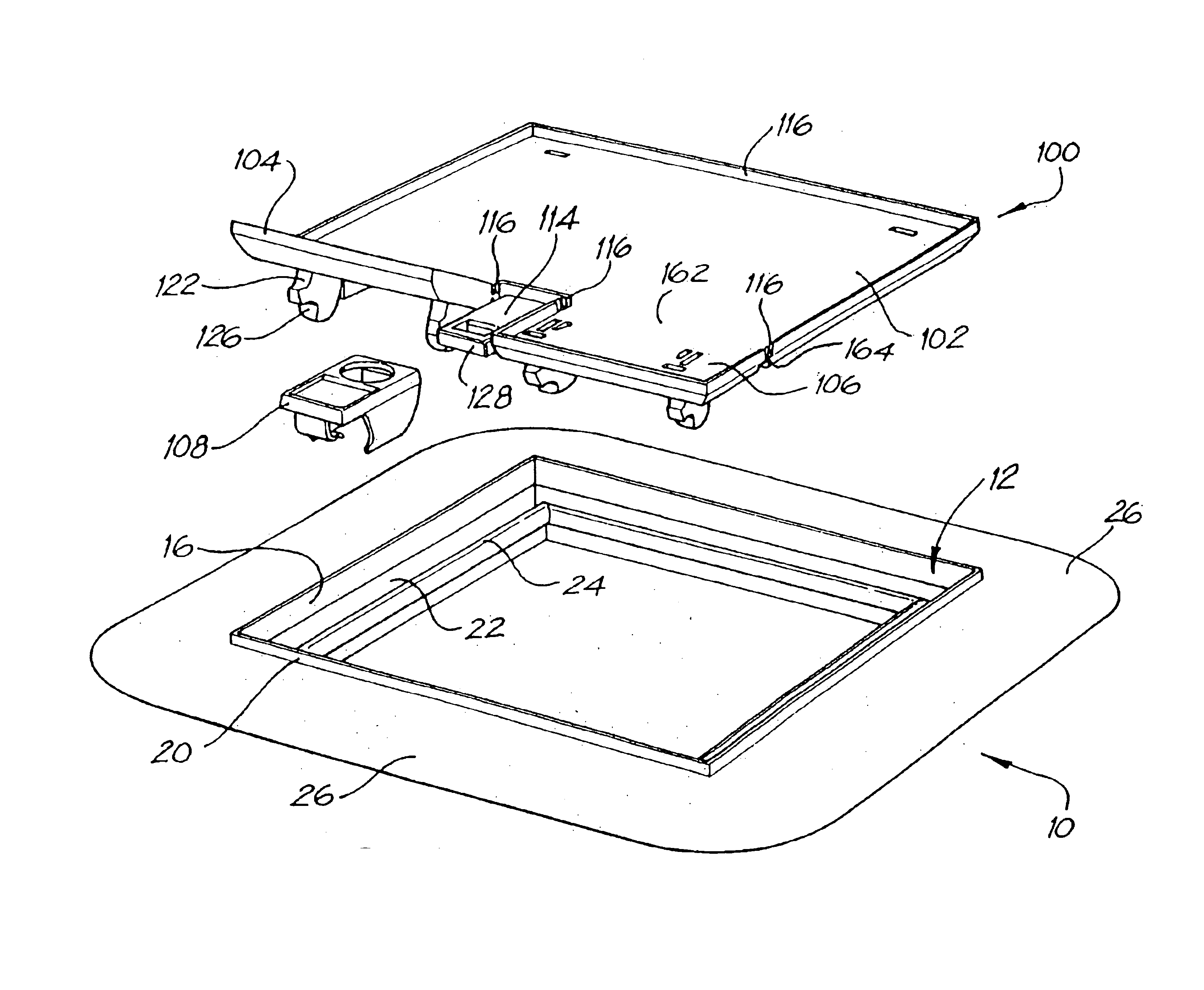
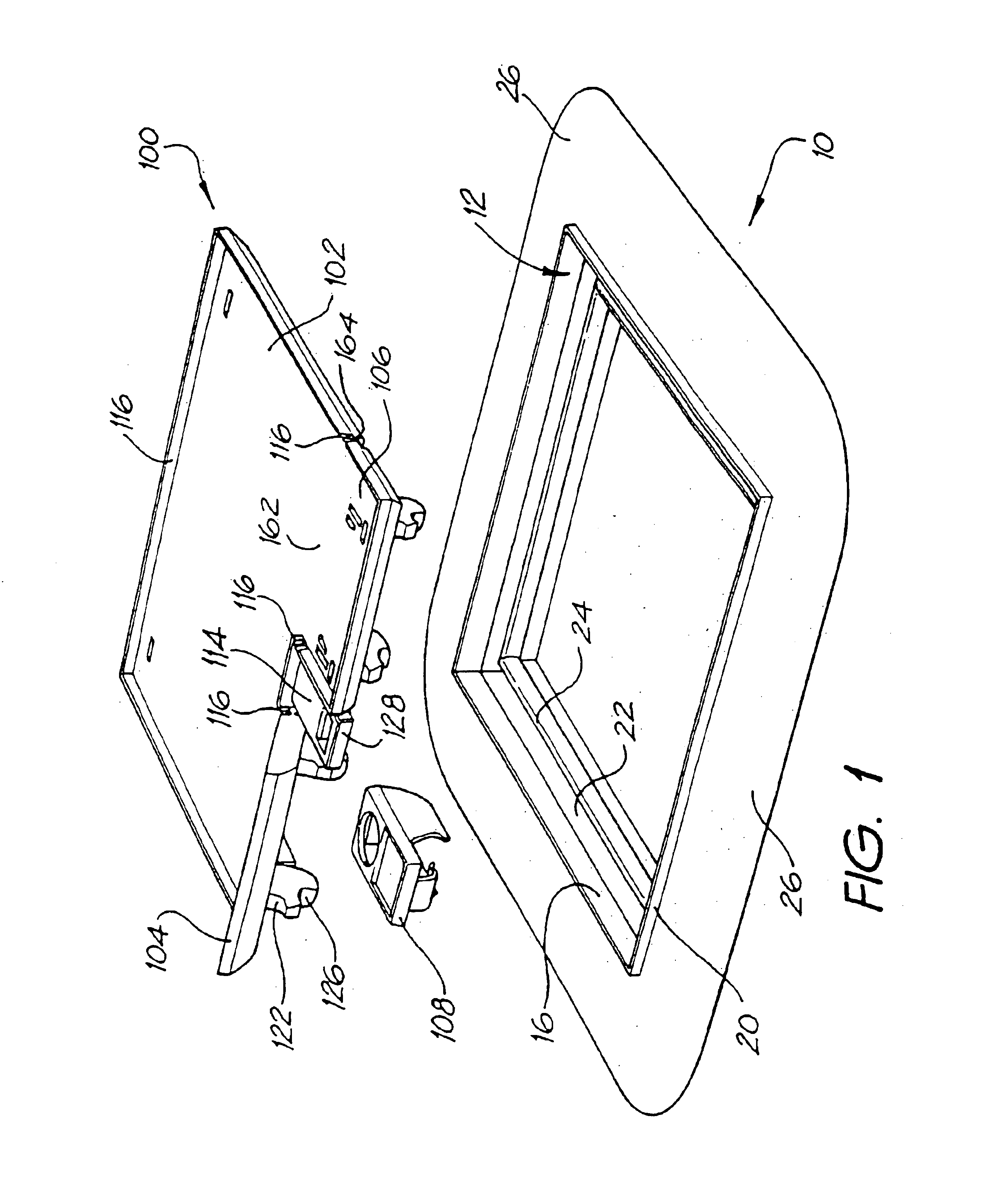
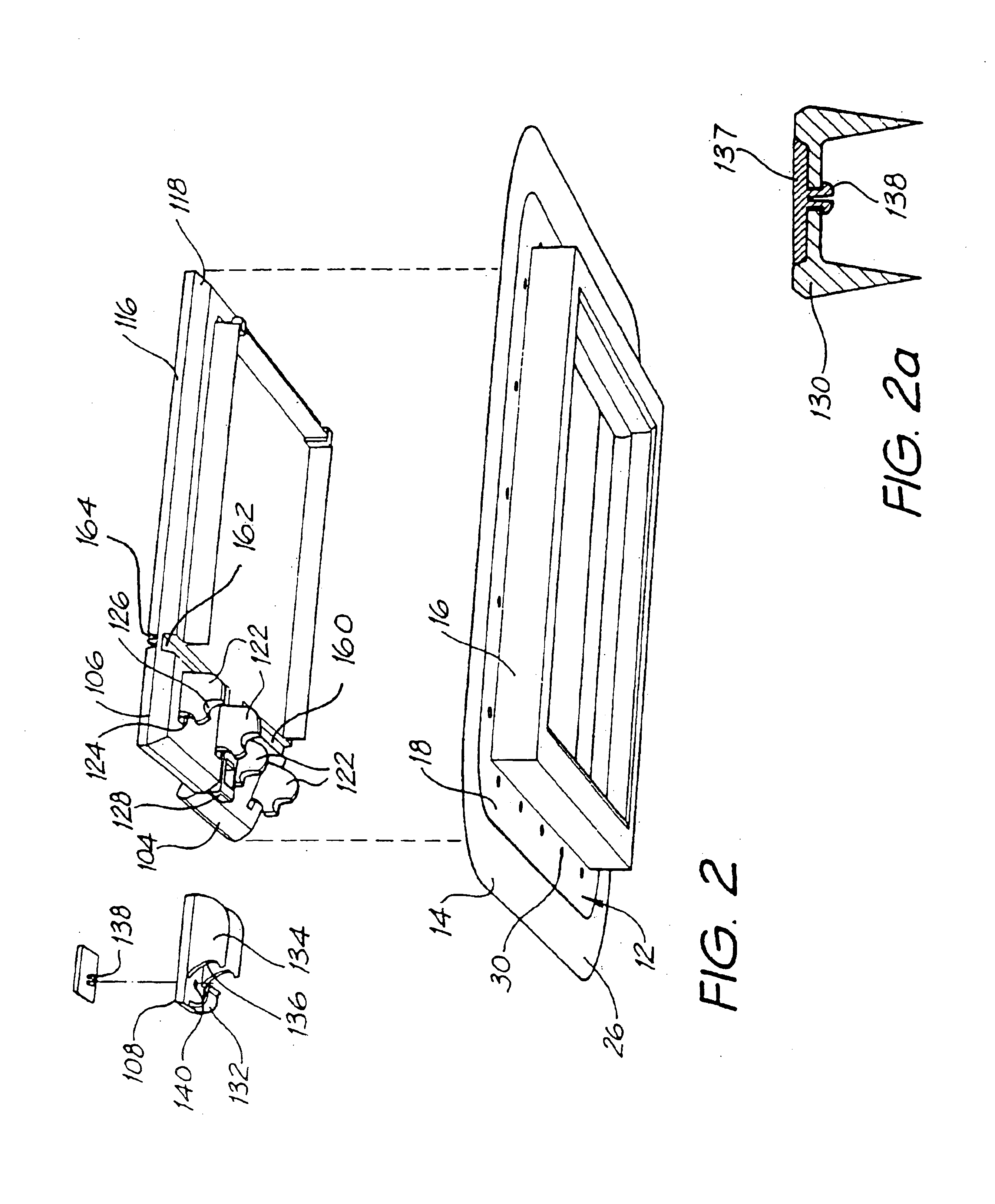
Referring to FIG. 1, the access panel comprises two sub-assemblies or components, a support frame 10 and a lid 100. Turning to consider the support frame 10 first, as is best seen in FIGS. 2 and 3, the support frame comprises a structural element or frame 12 and a flexible overmoulding 14. The frame is generally square. The structural element is manufactured from a rigid high strength material such an engineering grade polymer (for example glass filled polypropylene or nylon), or more preferably die cast metal such as aluminium or zinc.

The structural element 12 of the frame includes a square frame element 16 which is adapted to locate inside an aperture in a floor, wall, desk or the like and an integral load bearing flange 18 which extends away from the outer edge of the frame element 16. This flange sits on the floor deck in use and supports the frame element. The load bearing flange 18 may be either screwed or glued to the floor deck. Fastening with screws facilitates removal and ...


PUM


Abstract

An access panel for providing access to cables, services or the like through an opening in a floor having a floor covering, is disclosed. The access panel includes a floor frame (10) located in the opening and a lid (100) supported on the frame (10). The frame (10) has a support flange (26) extending around its periphery which extends between the floor covering and the floor deck. The flange (26) provides a ramped edge tapered substantially uniformly over a distance of between 10 and 20 times the maximum thickness of the flange (26). The outermost part of the flange (26) is typically formed from a flexible polymeric material. A rib (20) extends around an aperture in the frame (10) and the height of the rib (20) is lower than the load bearing surface of the floor. The hinge (24, 120) is generally square and defines a pivot surface which extends parallel to and is spaced inwardly from an inner edge of the frame (10). A lid (100) for closing the aperture defines a bearing surface (120) which is adapted to slidably engage on the pivot surface (24) to allow the lid (100) to bear and pivot about the pivot surface (24). The lid (100) includes hatches (104, 106) which are moveable between an open position in which there is an aperture in the lid (100) through which cable services may extend and a closed position in which there is no aperture. Locking means (124, 126) are provided between the hatch (104, 106) and the frame (10) to lock the hatch (104, 106) in place in both the open and closed positions.

Description

FIELD OF THE INVENTIONThis invention relates to an access panel for an outlet for cable services through a barrier such as a floor, wall, ceiling, desktop or the like.BACKGROUND OF THE INVENTIONModern offices house an extensive array of electronic and electrical equipment which require both power supply and interconnecting communications cabling. As a result, such buildings commonly incorporate a hollow raised floor which provides cavities / ducts along which the cabling travels. The transition of power, phone lines, data cables and the like from the sub floor cavities / ducts is achieved through recessed compartments commonly known as floor boxes. An example can be seen in PCT / GB92 / 011011 (AU 19759 / 92). Floor boxes generally incorporate a frame which extends around an aperture in the barrier. For floors the frame is typically clamped between the floor surface and the underside of the floor deck which may be made of particle board, metal, cementitious materials or a combination thereof....

Claims


Application Information

Patent Timeline
IPC IPC(8): E04F19/08H02G3/18
CPCE04F19/08Y10T16/525H02G3/283H02G3/185
Inventor BOYD, MICHAEL DAVIDWHITE, IAIN KILBURN
Owner CABSCAPE HLDG
Why Eureka
Try Eureka