
Coleman regenerative engine with exhaust gas water extraction

a regenerative engine and exhaust gas technology, applied in the field of gas turbine engines, can solve the problems of complex structure and well-known capabilities of components, and achieve the effect of delivering power efficiently and increasing thermodynamic efficiency

Inactive Publication Date: 2005-02-01
COLEMAN RICHARD R +1
View PDF3 Cites 39 Cited by
  • Summary
  • Abstract
  • Description
  • Claims
  • Application Information

AI Technical Summary

Benefits of technology

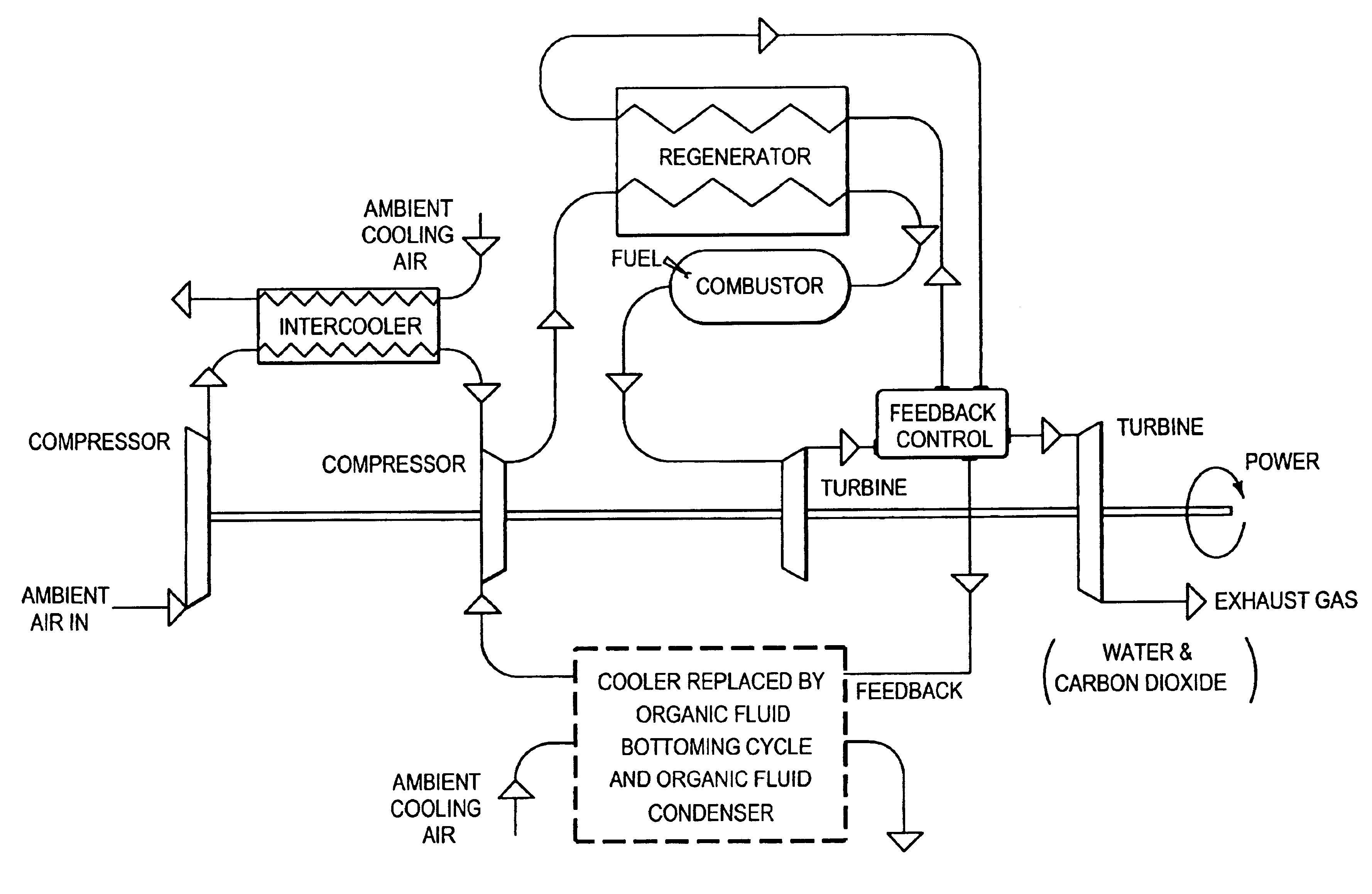
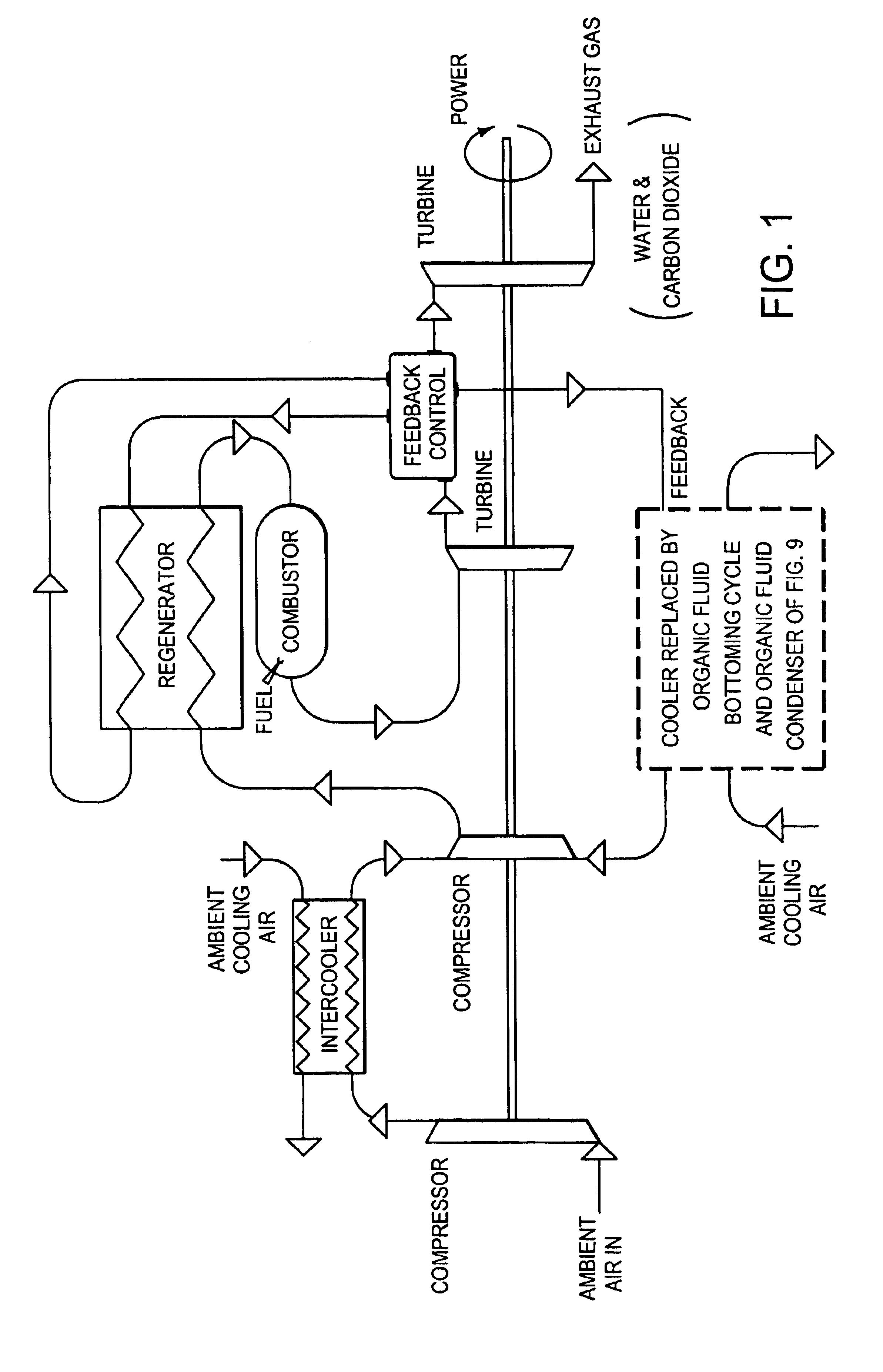
In simple terms, a bottoming cycle to increase thermodynamic efficiency, and a condensing unit to recover water from the products of combustion are preferably added to a basic but novel controlled feedback regenerative turbine engine, also referred to herein as the regenerative engine. The resulting configuration is unique in that it can deliver power efficiently while producing significant amounts of potable water, features that can be a priceless combination in drought-ridden areas or desert regions.

Problems solved by technology

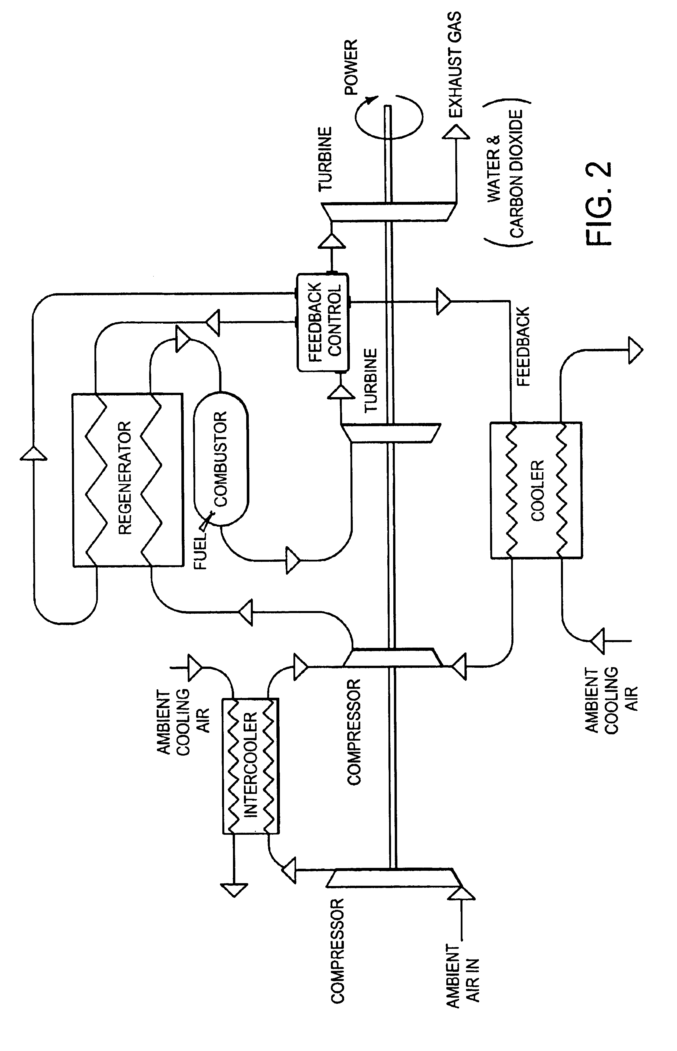
In that sense, the configuration is quite different from conventional through-flow designs; however, the components are well within known capabilities.

Method used


Image

  • Coleman regenerative engine with exhaust gas water extraction
  • Coleman regenerative engine with exhaust gas water extraction
  • Coleman regenerative engine with exhaust gas water extraction

Examples


Embodiment Construction

The system may be optimally sized for roughly 10,000 KW for each unit, but a unit can be sized to accommodate particular user recommendations and needs. The concept does not generally change with size. Size might well be chosen to promote design for mass production of units that can be interchanged easily to facilitate maintenance or permit transportability from one region to another within a power grid. Equally important, the size choices can also facilitate application to wide areas of market interest.

Components

Conventional components are, for the most part, all that is needed. Preferred compressors are well within the state-of-the-art, with some engineering required only for matching and for variations in flow; anticipated stage pressure ratios are well within current practice parameters. Turbines are also well within state-of-the-art, with operating temperatures well below levels that might otherwise require special cooling, with engineering only required to accommodate variatio...


PUM


Abstract

An improved turbine engine topology, wherein the improvement comprises a repositioning, with respect to a conventional intercooled regenerative turbine engine topology, of exhaust gas output from a low pressure turbine stage to a regenerator, to an exhaust gas output from a high pressure turbine stage to the regenerator. The engine topology may additionally employ, as an intermediate stage between the high pressure turbine and the low pressure turbine, a feedback control system, whereby the exhaust gas output from the high pressure turbine stage to the regenerator flows through the feedback control. The engine topology may advantageously also employ an additional cooler and an additional exhaust gas output in the feedback control, whereby exhaust gas flows from the feedback control through the additional cooler to a high pressure compressor stage, or the exhaust gas can flow from the feedback control through a bottoming cycle to the high pressure compressor stage. An exhaust gas condenser may advantageously be placed into the bottoming cycle system. The bottoming cycle / condenser improvements may alternatively be effected an other wise conventional intercooled regenerative turbine engine topology.

Description

TECHNICAL FIELDThe invention relates to the field of gas turbine engines and to the field of power generation and to water reclamation; more particularly, it relates to method and apparatus for a gas turbine regenerative engine with exhaust gas water extraction.BACKGROUND OF THE INVENTIONVariations of Gas TurbinesThere are many variations on simple cycle gas turbines. Each offers something special, be it operating economies or features that meet specific needs. The features might be small size, lightness in weight, high reliability, simplicity, or another measurable attribute. Emphasis is often placed on performance and power density, and achieving these objectives through use of known technologies and sound design principles for compressors, turbines, combustors, heat exchangers, and technology from related conventional materials sciences would be desirable. It is expected that achieving large gains requires the component arrangement to be new and different, to depart significantly...

Claims


Application Information

Patent Timeline
Patent Type & Authority Patents(United States)
IPC IPC(8): F02C3/00F02C7/143F02C3/13F02C7/08F02C6/18F02C7/10F02C3/34F02C7/12
CPCF02C3/13F02C3/34F02C6/18F02C7/10F02C7/143F02C7/08Y02T50/671Y02T50/676F05D2260/232F05D2270/07F05D2270/053F05D2260/10Y02T50/60
Inventor COLEMAN, RICHARD R.COLEMAN, THELMA
Owner COLEMAN RICHARD R
Learn More