Method and device for inspecting pipelines

a pipeline and pipeline technology, applied in the direction of sensors ultrasonic/sonic/infrasonic wave generation, etc., can solve the problems of only detecting corrosion and pitting, and the prior art method or device is difficult to detect small pittings, so as to improve the resilience and damping properties, prevent the bouncing of the articulated sensor suspension, and reduce the effect of bouncing

Inactive Publication Date: 2005-02-01
PII PIPETRONIX
View PDF15 Cites 83 Cited by
  • Summary
  • Abstract
  • Description
  • Claims
  • Application Information

AI Technical Summary

Benefits of technology

To guarantee resilient coupling between the sensor arrays and the pipe wall while preventing bouncing of the articulated sensor suspension at non-circular shapes of the pipeline, e.g. at bulges as well as, in particular, radial oscillating motion of the sensor suspension, the invention furthermore provides that the articulated arm hinged to the central element is formed as telescopic spring element having additional damping properties. To improve the resilient and damping properties, a further telescopic spring element can be provided between the sensor rocker and elements of the sensor suspension.
The sensor rocker receives the array-shaped measuring sensors and is accordingly preferably formed such that a curvature of the surface facing the inner wall of the pipe of the sensor rockers in the peripheral direction corresponds substantially to the curvature of the sensor array. In a further embodiment of the invention, the sensor rockers have a surface groove extending in the peripheral direction into which the sensor arrays are fitted, wherein the depth of the groove corresponds substantially to a radial dimension of the sensor array. In accordance with a further preferred embodiment of the inventive device, the sensor rockers are oversized compared to an axial dimension of the sensor array. In a highly preferred embodiment, spacers are disposed in the oversized regions. This guarantees a fixed, final separation between the sensor arrays and the inner wall of the pipeline which improves the quality of the measuring results and also protects the measuring sensors, in particular from mechanical damage. In accordance with a further feature, the inventive device has a wear protection on the surface of the spacers facing the pipe wall to prolong the length of time during which the method and device in accordance with the invention can be used. The wear protection can consist e.g. of wear-resistant plastic material, e.g. polyurethane.

Problems solved by technology

Disadvantageously, small pittings are difficult to detect.
Disadvantageously, the above-described prior art method or device only detects corrosion and pitting, however not cracks.

Method used


Image

  • Method and device for inspecting pipelines
  • Method and device for inspecting pipelines
  • Method and device for inspecting pipelines

Examples


Embodiment Construction

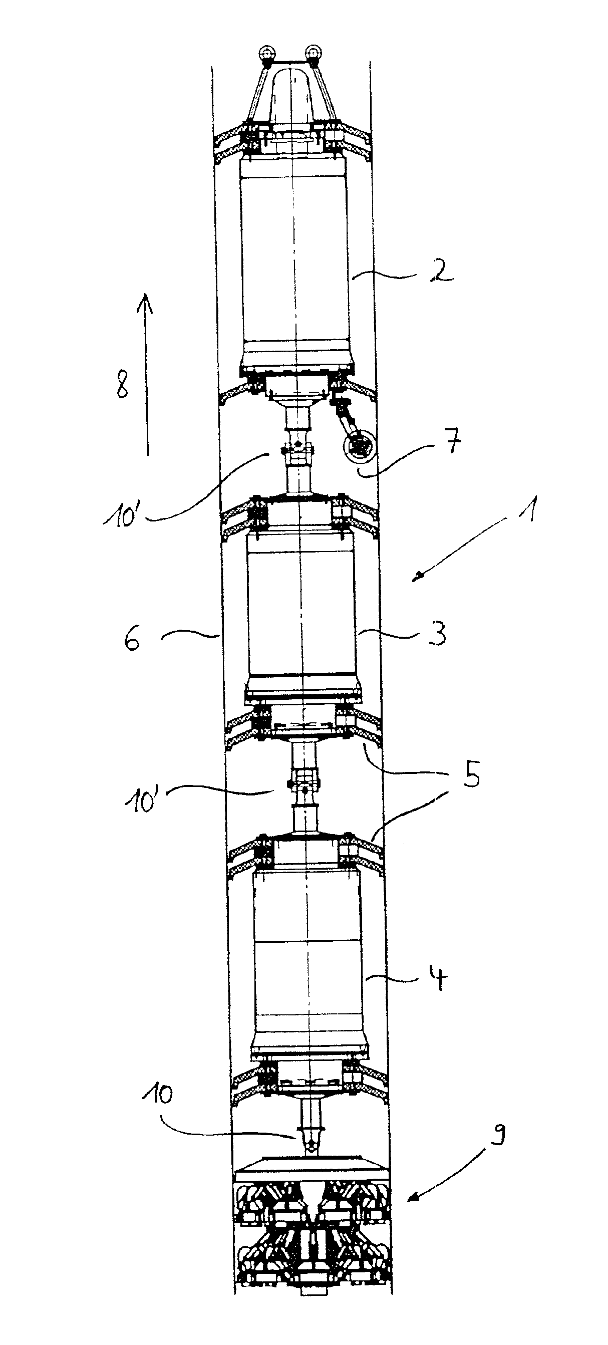
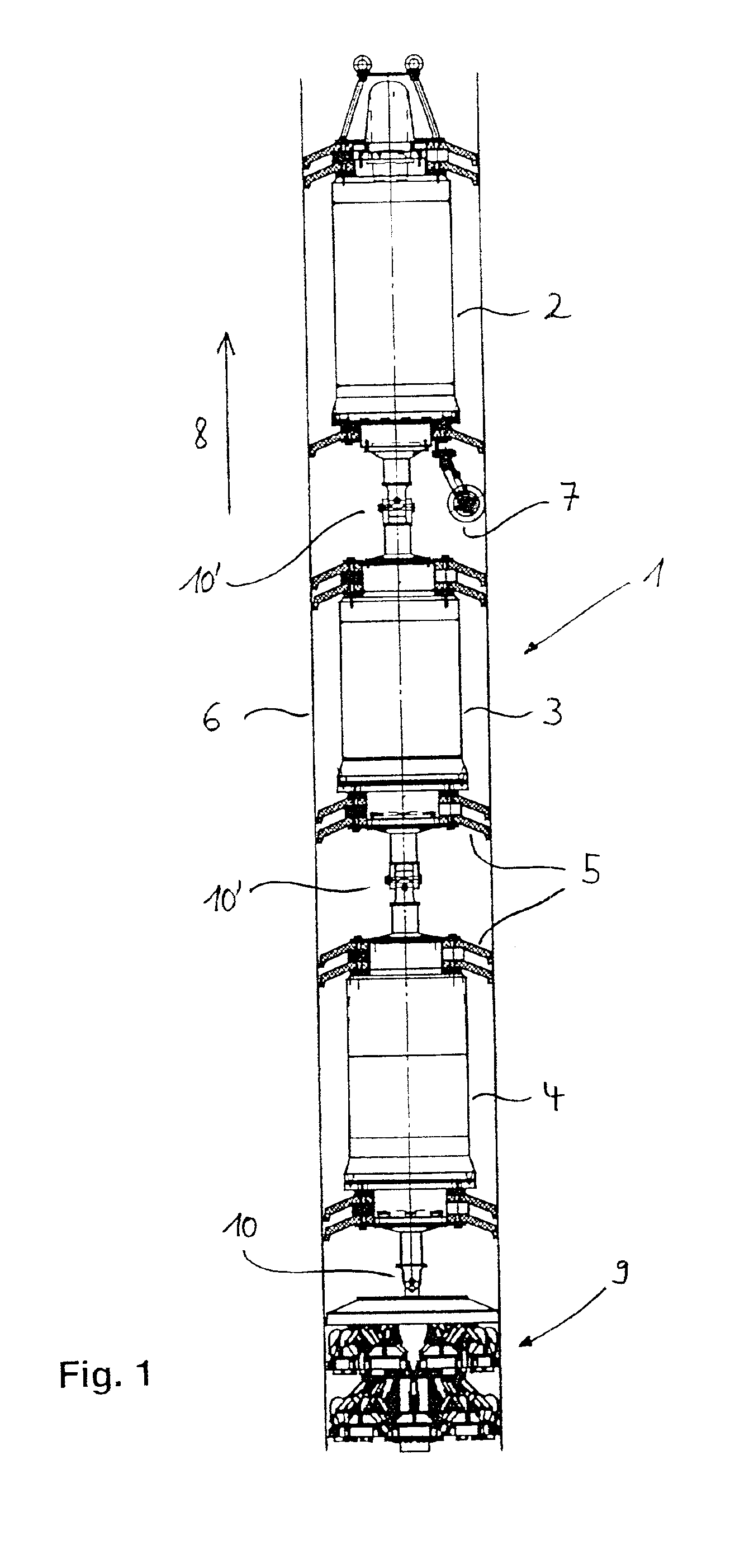
In the embodiment of FIG. 1, a device for passage through a pipeline, a so-called pig 1, comprises three sequential bodies 2, 3 and 4 each having one pressure-tight casing. The casings of the bodies 2, 3 and 4 have several collars 5 which abut the inside of the pipeline 6 to advance the pig 1 by means of the medium transported in the pipeline. Batteries are e.g. located in the casing of the body 2 for supplying the device with electricity. Moreover, the body 2 has at least one roller 7 constituting an odometer wheel for measurement of the path length. The casing of the second body 3 receives means for data processing and recording whereas the casing of the last downstream body 4 (direction of movement 8 of the device) comprises a measuring electronics for the sensor device described below.

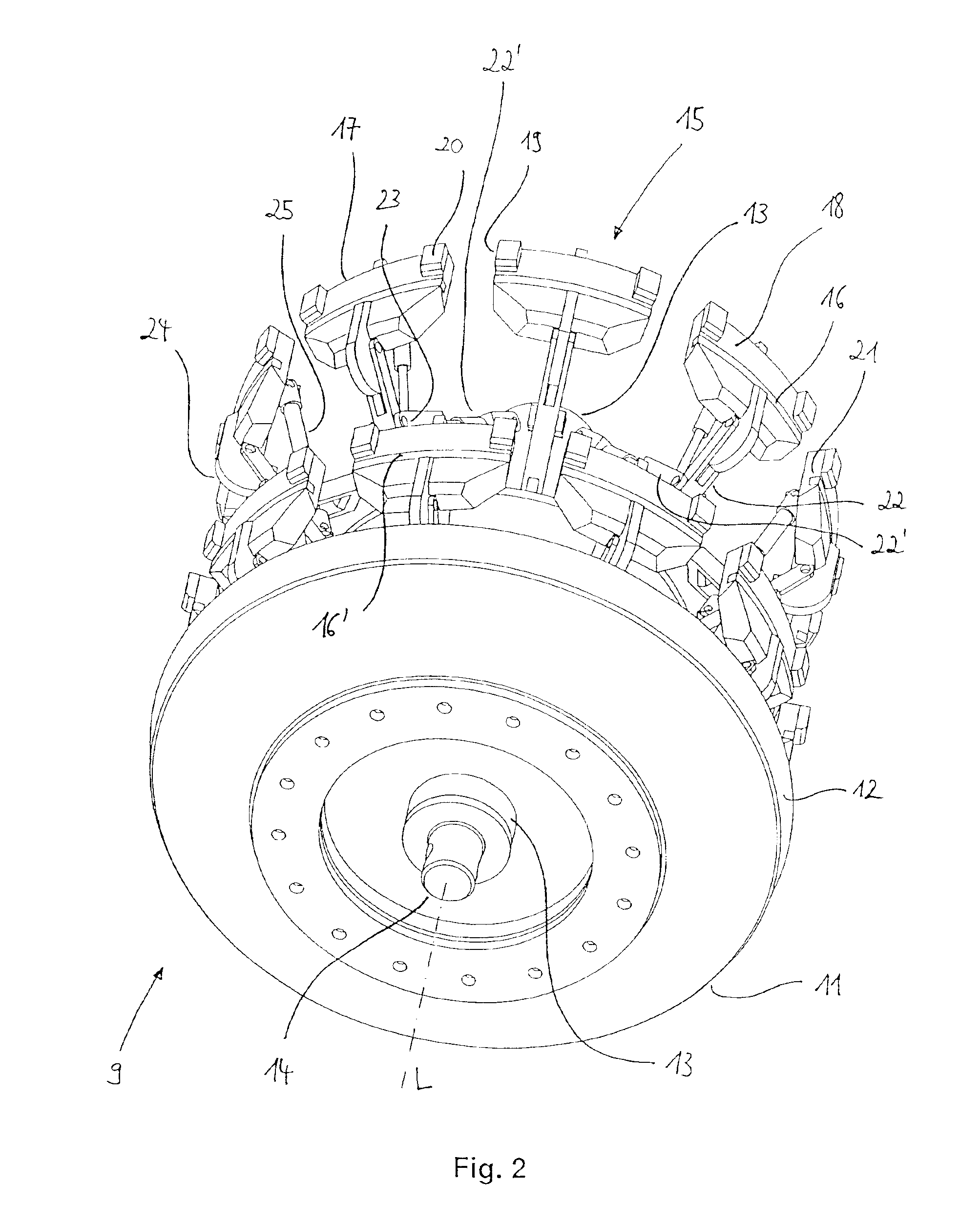
The trailing end of the pig 1 of the embodiment shown in FIG. 1 comprises an inventive device 9 for inspecting pipelines with a sensor support and measuring sensors 16, 16′ (FIG. 2) supported there...


PUM

PropertyMeasurementUnit
angleaaaaaaaaaa
angleaaaaaaaaaa
angleaaaaaaaaaa

Abstract

The invention concerns a method and a device for inspecting pipelines, in particular for detecting defects in pipelines by means of ultrasound. Towards this end, measuring sensors transmit ultrasound signals during passage through a pipeline. The signals reflected on boundary regions of a pipeline wall, e.g. surfaces or defects, are then measured and evaluated. The invention is characterized in that partial regions of the measuring sensors (virtual sensors) formed of a plurality of neighboring sensor elements irradiate ultrasound signals into the pipe wall at at least one radiation angle which is inclined with respect to the normal to the pipe wall and the signals reflected at boundary regions of the pipe wall are received by same and/or other partial regions of the respective measuring sensors, wherein defects in the pipe wall are determined by evaluation of the acoustical signals reflected by different boundary regions.

Description

This application claims Paris Convention priority of DE 102 02 432.4 filed Jan. 22, 2002 the complete disclosure of which is hereby incorporated by reference.BACKGROUND OF THE INVENTIONThe invention concerns a method for inspecting pipelines, in particular for detecting material faults in pipelines using ultrasound, wherein measuring sensors transmit ultrasound signals during passage through a pipeline, and signals reflected on boundary regions, such as surfaces or defects of a pipe wall are measured and evaluated. The invention also concerns a device for inspecting pipelines, in particular as part of a device which is passed through a pipeline, with at least one sensor support having measuring sensors which are arranged substantially circularly around the sensor support.Laid pipelines require regular automized damage-free inspection for corrosion, pitting or the like. These defects can be determined by observation of associated pipe wall thickness variations and by their physical p...

Claims


Application Information

Patent Timeline
Patent Type & Authority Patents(United States)
IPC IPC(8): G01N29/26G01N29/34G01N29/24G01N29/07G01N29/04
CPCG01N29/07G01N29/2456G01N29/262G01N29/341G01N2291/2636G01N2291/0421G01N2291/0422G01N2291/044G01N2291/106G01N2291/0235
Inventor KRIEG, WOLFGANGHUGGER, ACHIM
Owner PII PIPETRONIX
Why Eureka
Try Eureka