Valve timing adjusting device

a timing adjustment and valve technology, applied in the direction of valve details, valve arrangements, non-mechanical valves, etc., can solve the problems of low durability, radio noise, deterioration of device durability, etc., to prevent the rotation of the input shaft, enhance or produce friction, and high accuracy

Inactive Publication Date: 2005-02-01
NIPPON SOKEN +1
View PDF11 Cites 21 Cited by
  • Summary
  • Abstract
  • Description
  • Claims
  • Application Information

AI Technical Summary

Benefits of technology

It is an object of the present invention to provide a valve timing adjusting device superior in durability.
According to another aspect of the present invention, the friction member is constructed by a resilient member which generates a frictional force by resilient deformation, thus simplifying the construction of the friction means.

Problems solved by technology

The device, however, has a problem where in controlling a phase change with high accuracy, it demands a certain stable condition need for controlling an oil pressure even when in an environment of low temperature or just after start-up of an engine.
The whole of the electric motor rotates together with a sprocket which receives the driving torque from the crankshaft, causing an inertia weight on the device to becomes large.
This leads to deterioration of the durability of the device.
Such a slide-contact connection member is apt to wear, bringing about low durability and radio noise.

Method used


Image

  • Valve timing adjusting device
  • Valve timing adjusting device
  • Valve timing adjusting device

Examples


first embodiment

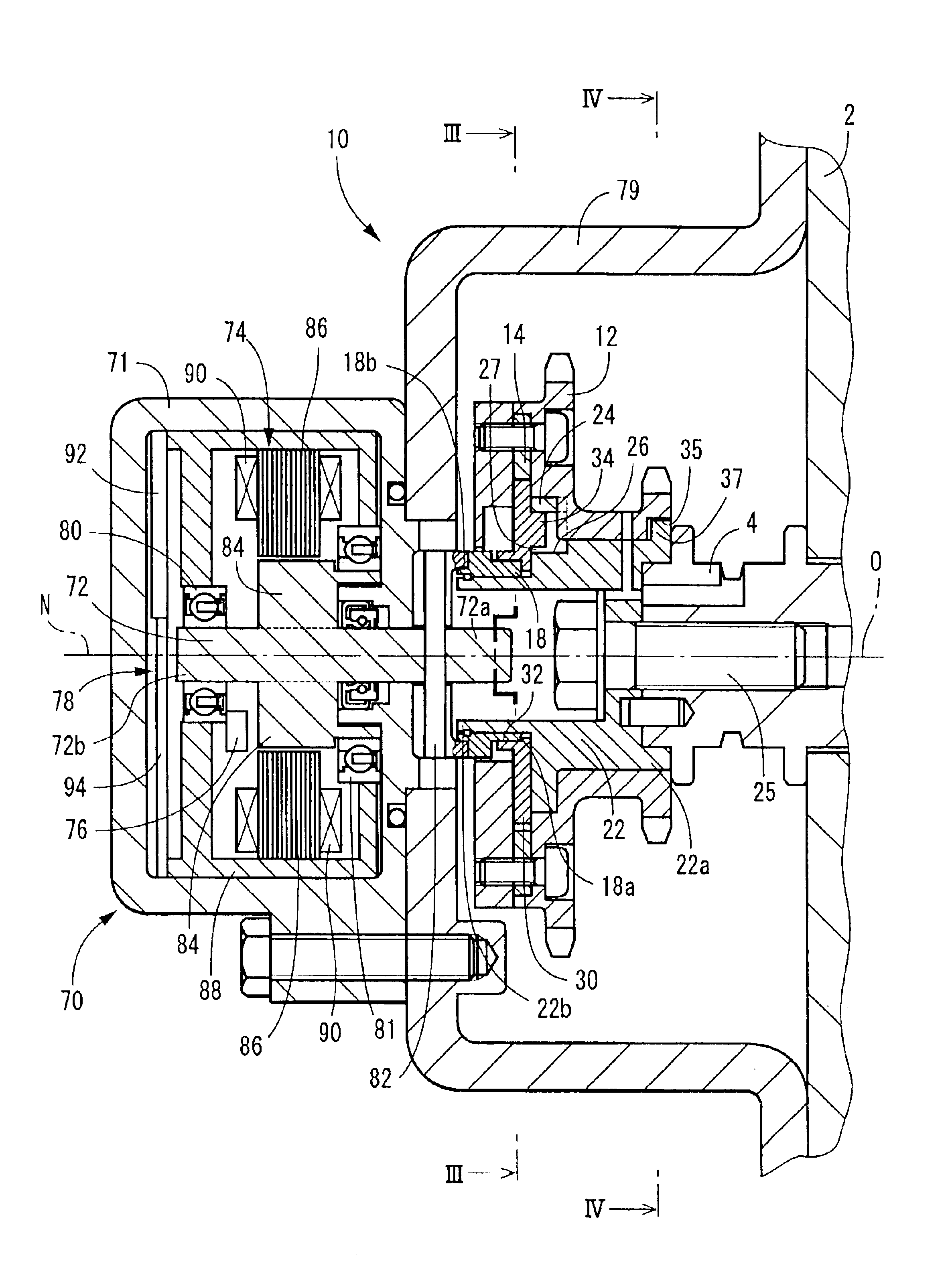
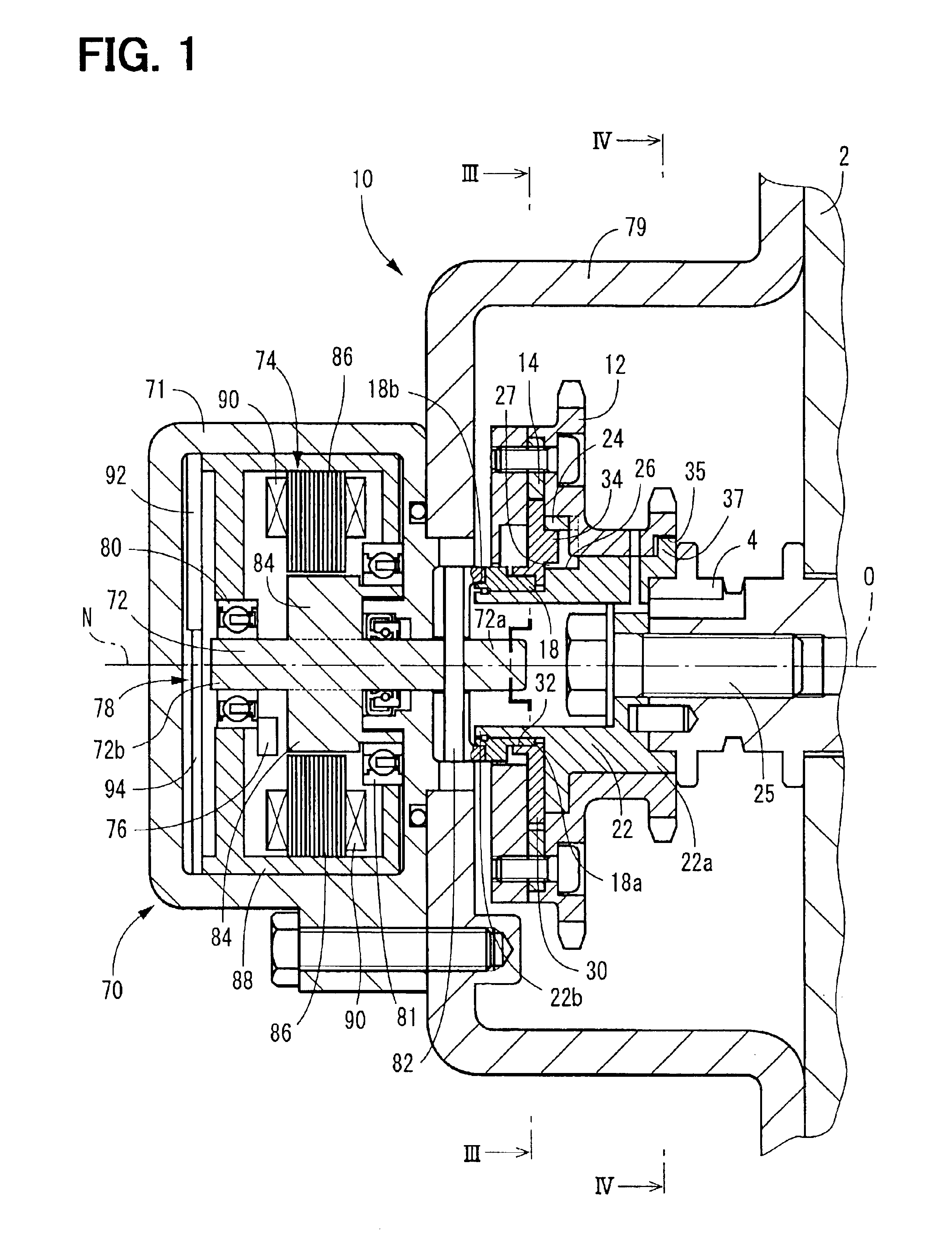
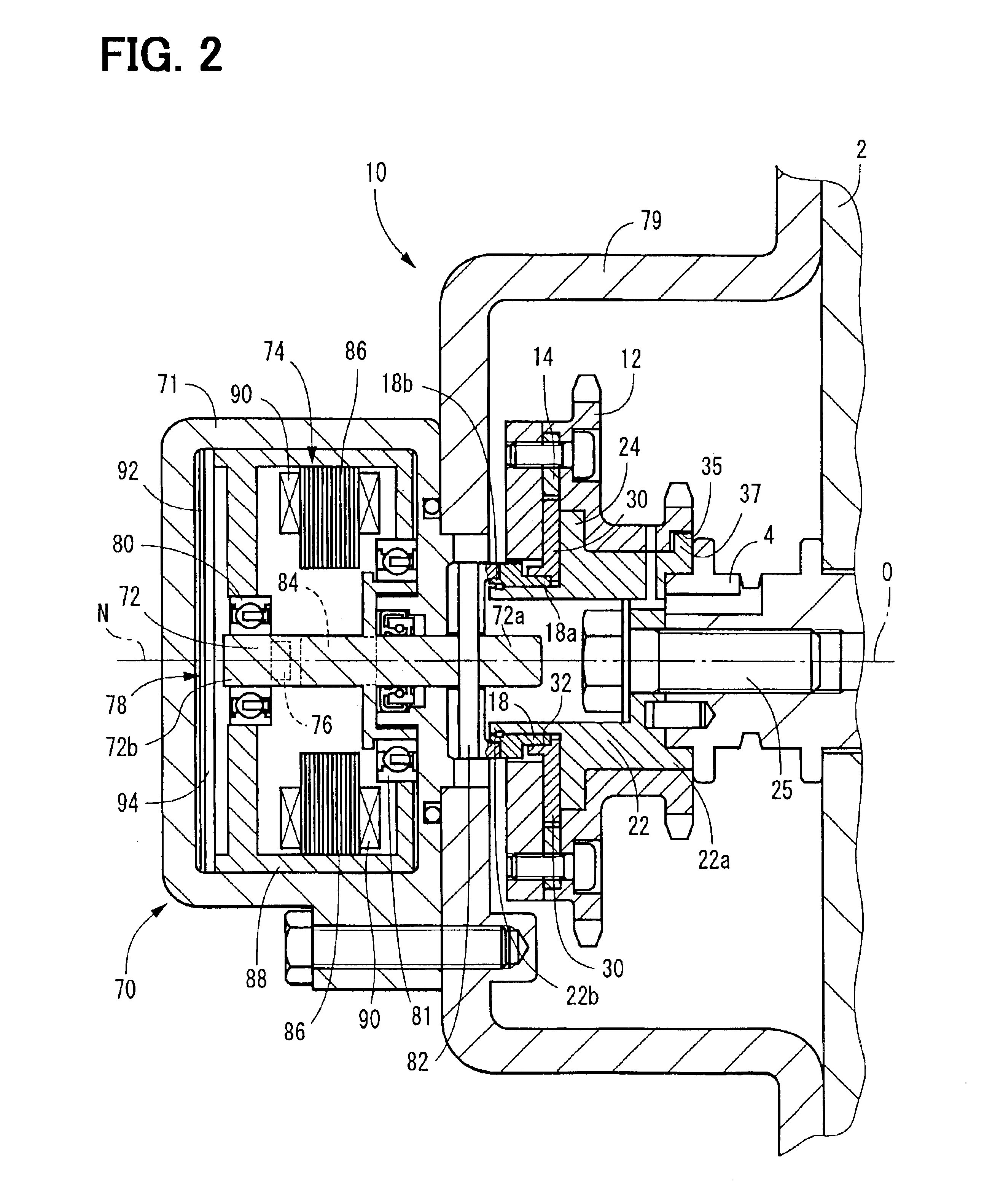
A valve timing adjusting device for an engine according to a first embodiment of the present invention is illustrated in FIGS. 1 to 4. The valve timing adjusting device 10 of this embodiment controls a rotational phase of a camshaft that drives intake valves of an engine 2, thereby it adjusts valve timing of the intake valves.

The valve timing adjusting device 10 is provided in a transmission system which transfers a driving torque on a crankshaft in the engine 2 to a camshaft 4 in the engine. The camshaft 4 is adapted to rotate about its axis O to open and close intake valves in the engine2. The axis O is referred to as a cam axis. The crankshaft of the engine 2 constitutes a drive shaft and the camshaft 4 constitutes a driven shaft.

A sprocket 12 is supported on an outer periphery wall of an output shaft 22 to be described later in a relatively rotatable manner about the cam axis O. A power transmitting member such as a chain, a gear train or a belt couples the sprocket 12 and the c...

second embodiment

A valve timing adjusting device according to a second embodiment of the present invention is illustrated in FIG. 6, in which substantially the same constituent portions as in the first embodiment are identified by like reference numerals.

In the valve timing adjusting device 100 according to this second embodiment, a coned disk spring 102 as a friction member is interposed between a planetary gear 30 and a sprocket 12. An end portion 102a on a large diameter side of the coned disk spring 102 is fixed to the sprocket 12, while an end portion 102b on a small diameter side of the coned disk spring 102 is pressed for sliding contact against an outer wall on an anti-engaging portion side of the planetary gear 30. According to this construction, when the planetary gear 30 tries to rotate relatively with respect to the sprocket 12, a frictional force proportional to a resilient characteristic of the coned disk spring 102 is generated in the slide contact portion between the coned disk sprin...

third embodiment

A valve timing adjusting device according to a third embodiment of the present invention is illustrated in FIGS. 7 and 8, in which substantially the same constituent portions as in the first embodiment are identified by like reference numerals.

In the valve timing adjusting device 150 of this third embodiment, an inner periphery wall of each of engaging holes 26 formed in an output shaft 22 is tapered so as to be larger in diameter toward an opening 27 side in which a corresponding engaging lug 34 in the planetary gear 30 is inserted. An outer periphery wall of each engaging lug 34 is tapered so as to be smaller in diameter toward a projecting tip portion 34a. Each engaging lug 34 is supported at a base portion 34b thereof by a body 31 of a planetary gear 30 so as to be movable to both sides in a central axis Q direction, and is urged in the direction of insertion into the corresponding engaging hole 26 by means of a coiled spring 152 as an urging means. In this embodiment, as shown ...


PUM


Abstract

A valve timing adjusting device adjusts valve timing by shifting rotational phase of a camshaft relative to a crankshaft. The device has an electric motor for rotating a rotor member that drives and moves a phase defining member to a required position. The phase defining member defines the rotational phase of the camshaft in accordance with the position itself. The phase defining member may be a planetary gear rotatably supported on an eccentric shaft as the rotor member. The planetary gear works as both a reduction mechanism and a phase shifting mechanism. The phase defining member may be a control pin slidably supported on a rotatable member as the rotor member. A planetary gear may be additionally used as the reduction mechanism for rotating the rotatable member. It is possible to control the phase with high accuracy and durability.

Description

CROSS REFERENCE TO RELATED APPLICATIONSThis application is based on Japanese Patent Applications No. 2002-117885 filed on Apr. 19, 2002 and No. 2002-318793 filed on Oct. 31, 2002 the contents of which are incorporated herein by reference.BACKGROUND OF THE INVENTION1. Field of the InventionThe present invention relates to a valve timing adjusting device for an internal combustion engine for adjusting an opening and closing timing of at least one of intake and exhaust valves. Hereinafter the internal combustion engine is referred to as an engine. The opening timing and the closing timing of at least one of the valves are referred to as valve timing.2. Description of Related ArtA valve timing adjusting device is known that is provided in a transmission system for transferring a driving torque of a crankshaft as an engine drive shaft to a camshaft as a driven shaft, and permits of adjustment of the camshaft functioning to open and close intake or exhaust valves in an engine. This valve ...

Claims


Application Information

Patent Timeline
Patent Type & Authority Patents(United States)
IPC IPC(8): F01L1/344F01L1/34F01L1/46
CPCF01L1/352F01L2250/02F01L2820/032
Inventor TAKENAKA, AKIHIKOADACHI, MICHIOINOHARA, TAKAYUKI
Owner NIPPON SOKEN
Why Eureka
Try Eureka