Electromagnetic fluid controller

a technology of electromagnetic fluid controller and actuator, which is applied in the direction of valve operating means/release devices, machines/engines, etc., can solve the problems of increased manufacturing costs and higher manufacturing costs, and achieve the effects of reducing the effect of dispersion delay in timing, increasing attraction force acting, and facilitating film formation

Inactive Publication Date: 2005-02-01
DENSO CORP
View PDF8 Cites 29 Cited by
  • Summary
  • Abstract
  • Description
  • Claims
  • Application Information

AI Technical Summary

Benefits of technology

In an electromagnetic fluid controller according to a first aspect of the invention, a valve needle opens and closes a fluid passage by being seated in and separated from a valve seat of a valve body. An armature is fixed to the valve needle on the side opposite to the valve seat. The armature faces a stator using a spring force of a spring positioned at a specified distance. Upon energization of a coil wound around a bobbin accommodated in the stator, the armature is attracted by the stator against the spring force of the spring, and the armature and the stator abut each other through a nonmagnetic material film formed on at least one of the abutting faces. Accordingly, the action force of magnetic attraction, which is caused by a residual magnetic flux generated between both the abutting faces of the armature and the stator upon deenergization of the coil, is restrained to thereby contribute to reducing the effect of the dispersion in delays in the timing of the separation of the armature from the stator.
In the electromagnetic fluid controller according to a second aspect of the invention, forming the nonmagnetic material film with a uniform thickness makes the distance between both the material surfaces of the armature and the stator uniform and in close proximity during the abutting of the armature. This creates the advantage of increasing the attraction force acting between the armature and the stator compared to the case when the distance between both the material surfaces is not uniform.
In the electromagnetic fluid controller according to a third aspect of the invention, forming the nonmagnetic material film on the entire face, on the side where the armature and the stator abut, makes it easier to form the...

Problems solved by technology

To provide a structure having the foregoing air gap GA, a difference in level, between the top face of the valve needle 30 abutting the bottom face of the bearing 37 and the top face of the armature 31 facing t...

Method used


Image

  • Electromagnetic fluid controller
  • Electromagnetic fluid controller
  • Electromagnetic fluid controller

Examples


first embodiment

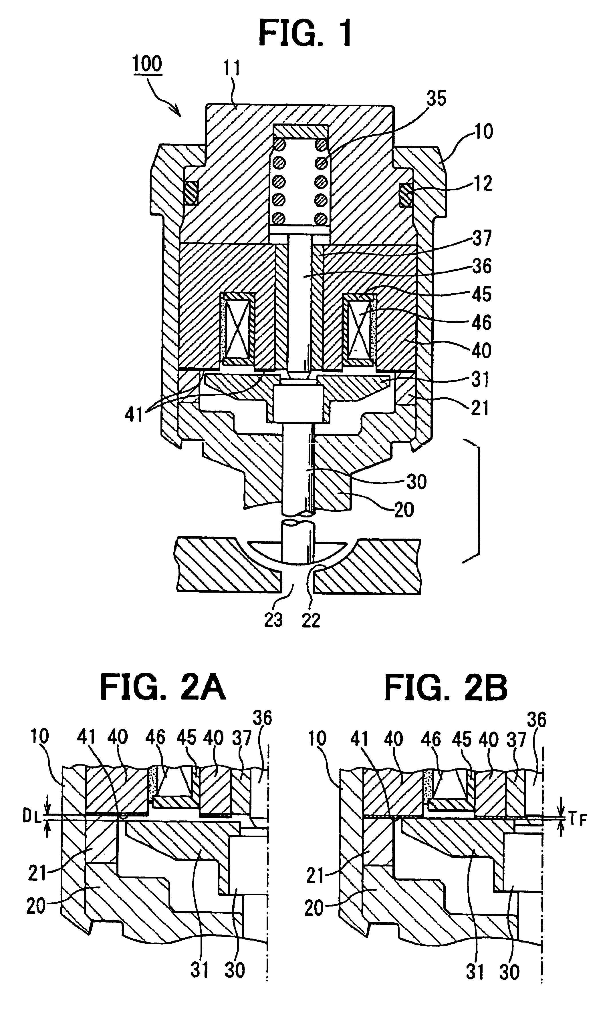
FIG. 1 is a cross-sectional view showing the main structural part of an electromagnetic fluid controller in a first embodiment of the present invention. In the drawings, similar structures or corresponding parts to those of the aforesaid conventional device are identified by like reference numerals and marks.

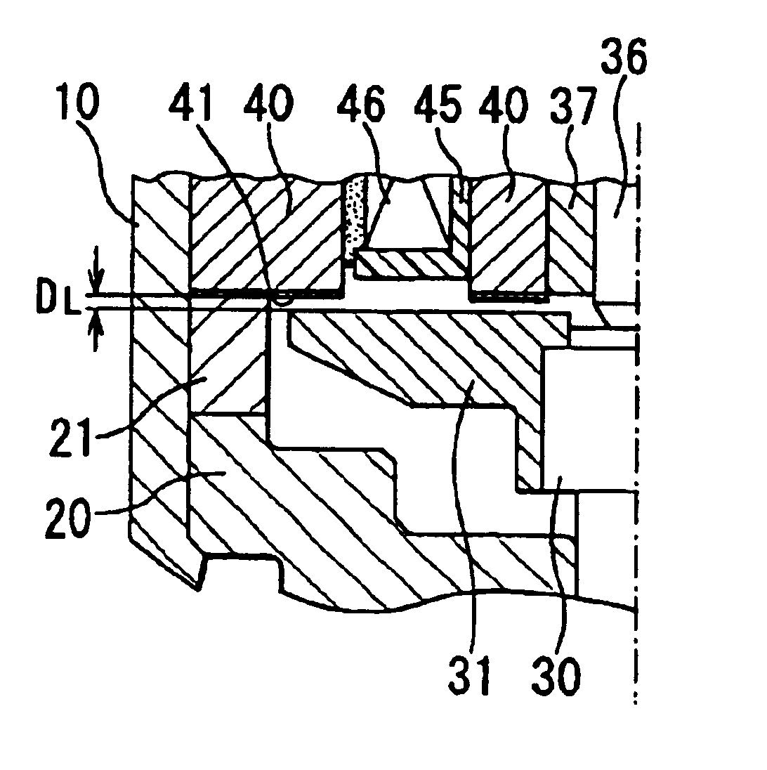
In FIG. 1, at one end of a valve body 20 of an electromagnetic fluid controller 100, a valve seat 22 having a fluid passage 23 is formed. A reciprocative valve needle 30 is inserted through the valve body 20 in a direction of the central axis thereof. As the valve needle 30 is seated in and separated from the valve seat 22 of the valve body 20, the fluid passage 23 is alternately closed and opened. An armature 31 is fixed by press-fitting it to the valve needle 30 on the side opposite the valve seat 22.

A stator 40 is arranged facing the armature 31 at a specified distance. In the entire area of the bottom face of the stator 40, a non-magnetic material film 41 is formed with a sp...

second embodiment

FIG. 5 is a cross-sectional view showing the main part structure of an electromagnetic fluid controller in a second embodiment of the present invention. In FIG. 5, in the structure of an electromagnetic fluid controller 200, a nonmagnetic material film 32 is formed on the top face of an armature 31 instead of the nonmagnetic material film 41 formed on the bottom face of the stator 40 in the first embodiment. FIG. 5 also shows a valve seat 22 and a fluid passage 23. Other parts are not changed, and therefore, the details on those parts will not be described here. With regard to the thickness and the material of the nonmagnetic material film 32, the same descriptions as in the above-mentioned first embodiment can be applied.

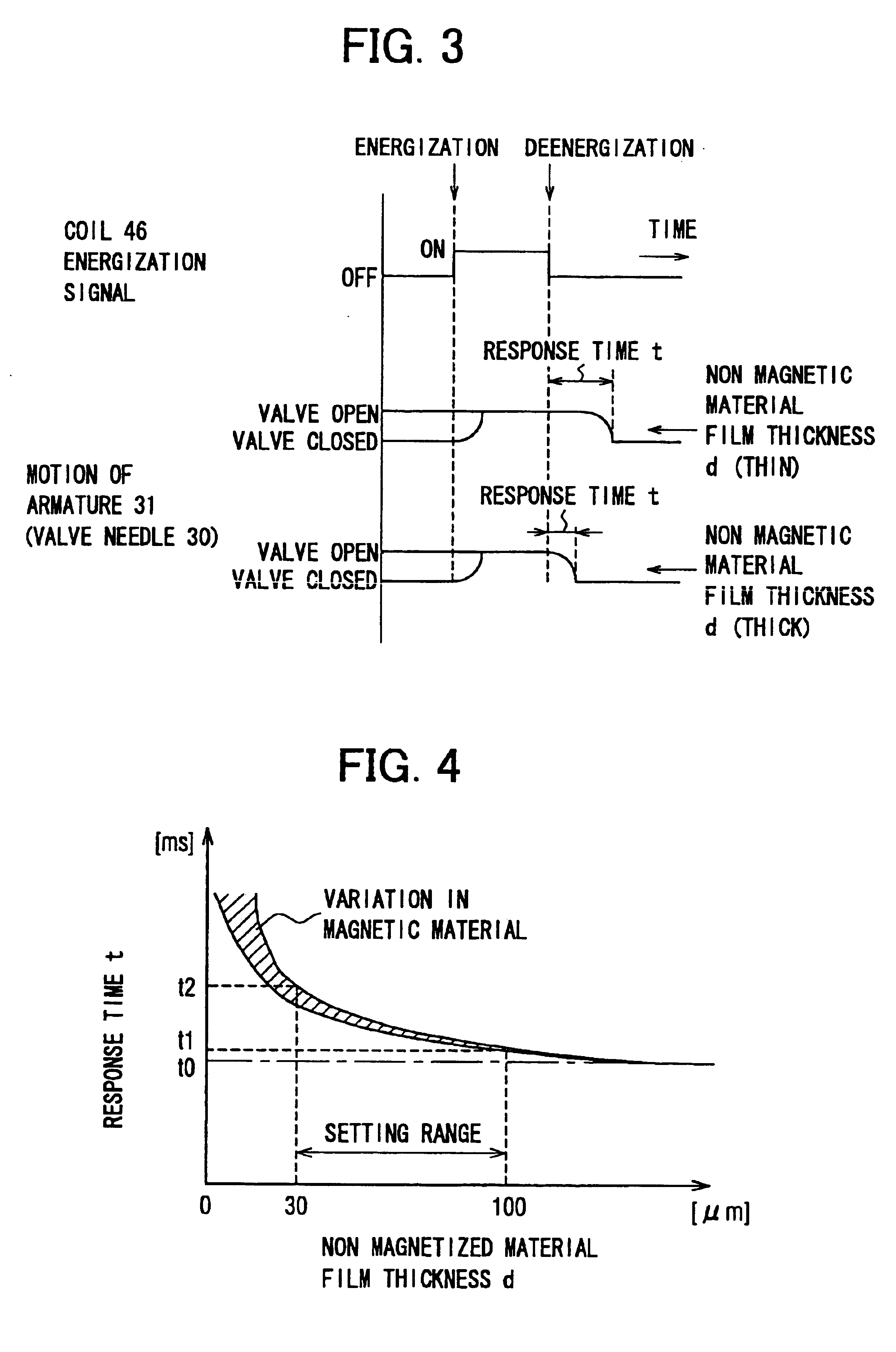
Next, the motion will be described referring to FIGS. 6A and 6B, which are enlarged partial cross-sectional views showing the motion of the armature 31 shown, in FIG. 5, having a fixed valve needle 30. FIG. 6A shows the state during deenergization of a coil 46, and...

third embodiment

FIG. 7 is a cross-sectional view showing the main part structure of an electromagnetic fluid controller in a third embodiment of the invention. In FIG. 7, in the structure of an electromagnetic fluid controller 300, nonmagnetic material films are formed on both abutting faces, which are a nonmagnetic material film 41 on the bottom face of a stator 40 and a nonmagnetic material film 32 on the top face of an armature 31. FIG. 7 also shows a valve seat 22 and a fluid passage 23. Other parts are not changed from the foregoing first and second embodiments, and therefore, the details on those parts will not be described here. With regard to the material of the nonmagnetic material film 32 and the nonmagnetic material film 41, the same descriptions as in the above-mentioned first and second embodiments are applicable.

Next, the motion will be described referring to FIGS. 8A and 8B, which are enlarged partial cross-sectional views showing the motion of the armature 31, shown in FIG. 7, havin...


PUM


Abstract

An electromagnetic fluid controller can prevent the action force of magnetic attraction between both abutting faces of an armature and a stator, and eliminate the necessity of a junction of the armature and a valve needle. Upon coil energization, the armature is attracted by an electromagnetic stator force, and the armature and the stator abut through a nonmagnetic material film. The nonmagnetic material film is formed of a material containing NiP on the end face of the stator with a thickness in a range from 30 to 100 micrometers. Thus, the action force of magnetic attraction between both the abutting faces upon deenergization of the coil can be prevented without providing an air gap, and delays in the timing of the separation of the armature from the stator can be decreased.

Description

CROSS REFERENCE TO RELATED APPLICATIONThis application is based upon, claims the benefit of priority of, and incorporates by reference the contents of prior Japanese Patent Applications No. 2001-267035 filed Sep. 4, 2001, and No. 2002-159824 filed May 31, 2002.BACKGROUND OF THE INVENTION1. Field of the InventionThe present invention relates to an electromagnetic fluid controller that controls the opening and closing of a fluid passage by using an electromagnetic drive.2. Description of the Related ArtA conventional type of an electromagnetic fluid controller 400 is known and is shown in a cross-sectional view in FIG. 9. In this controller, upon energization of a coil 46, an armature 31 is attracted by an electromagnetic force generated at a stator 40, and then a valve needle 30 in one body with the armature 31 turns from being seated in a valve seat (not shown) formed at one end of a valve body 20 to being separated from the valve seat so that a fluid passage is opened.FIGS. 10A and...

Claims


Application Information

Patent Timeline
IPC IPC(8): F16K31/06H01F7/08H01F7/16
CPCF02M63/0019F02M63/0024F02M63/0075H01F7/081H01F7/1638F16K31/0655F02M2200/9038F02M2200/9069F02M2200/07
Inventor MAKINO, TADAAKI
Owner DENSO CORP
Why Eureka
Try Eureka