Sensor for a variable displacement pump

a variable displacement, sensor technology, applied in the direction of positive displacement liquid engines, pump parameters, liquid fuel engines, etc., can solve the problems of affecting the operation of the sensor, difficult and expensive to obtain an effective seal between the pump housing and the member projecting outside the pump housing, and significant increase in the overall cost of the pump

Inactive Publication Date: 2005-02-01
CATERPILLAR INC
View PDF11 Cites 20 Cited by
  • Summary
  • Abstract
  • Description
  • Claims
  • Application Information

AI Technical Summary

Benefits of technology

One aspect of the present invention is directed to a sensor for a variable displacement pump having a housing containing a swashplate that is adapted to rotate about an axis. The sensor includes a magnet connected to the swashplate to rotate with the swashplate. A semiconductor chip is disposed prox

Problems solved by technology

However, the known sensors that are based on these principles are either unsuitable for use in a variable displacement pump or result in a significant increase in the overall cost in the pump.
However, obtaining an e

Method used


Image

  • Sensor for a variable displacement pump
  • Sensor for a variable displacement pump
  • Sensor for a variable displacement pump

Examples


Embodiment Construction

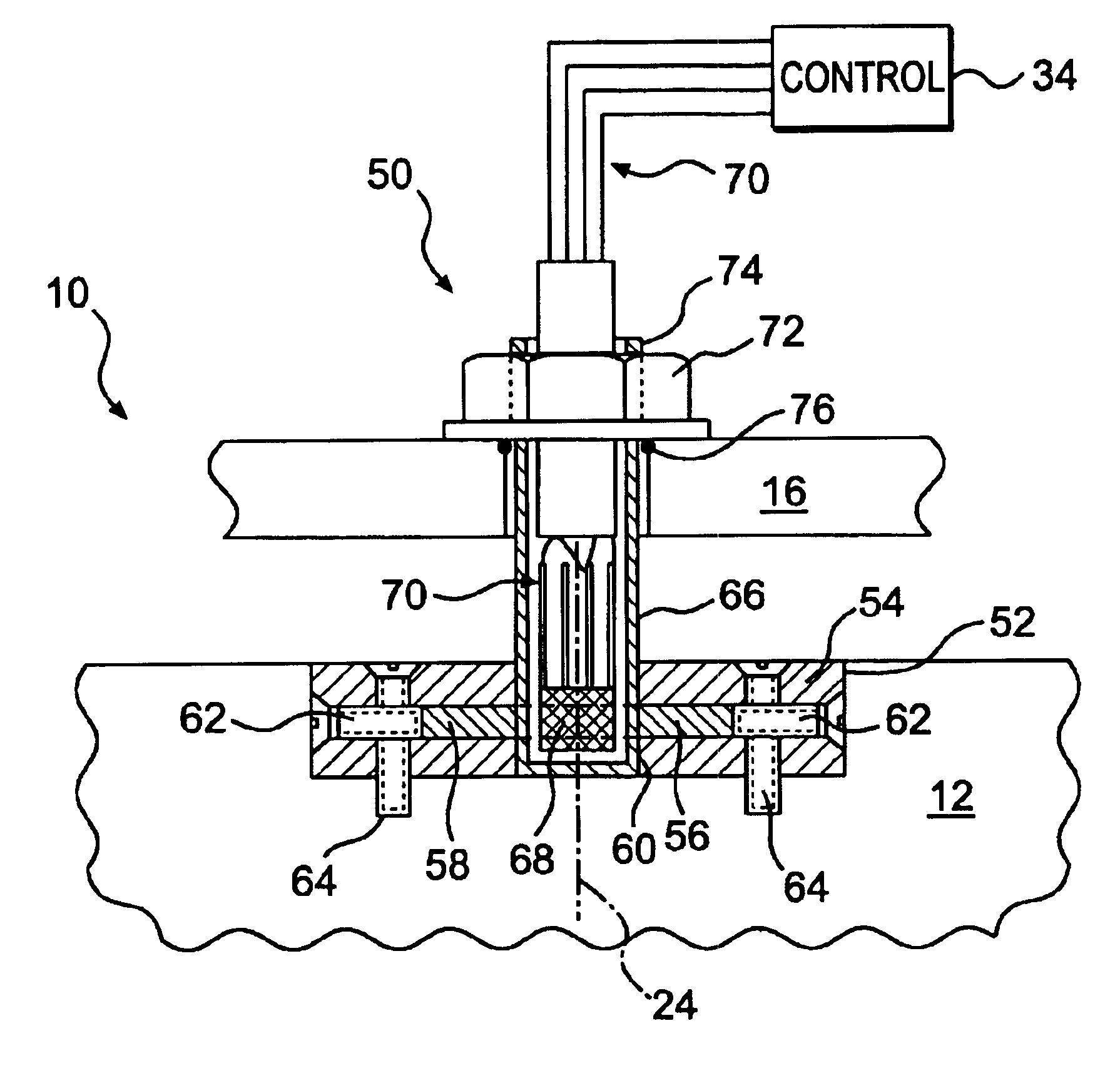
An exemplary embodiment of a variable displacement pump 10 is illustrated in FIG. 1. As shown, pump 10 includes a block 20 that is disposed in a housing 16 to rotate about a block axis 22. Block 20 defines a series of chambers 28, two of which are illustrated in FIG. 1. Each chamber includes an outlet port 30.

Pump 10 also includes a series of pistons 18. One piston 18 is slidably disposed in each chamber 28. The piston 18 is typically held against the swashplate 12 using either a fixed clearance device or a positive force hold-down mechanism (not shown) through a slipper 26.

A shaft (not shown) may be connected to block 20. A rotation of the shaft causes a corresponding rotation of block 20 about block axis 22. The shaft may be driven by an engine 14. Engine 14 may be, for example, an internal combustion engine. One skilled in the art will recognize, however, that the shaft may be driven by another type of power source, such as, for example, an electrical motor.

Pump 10 also includes ...


PUM


Abstract

A sensor for a variable displacement pump is provided. The pump has a housing containing a swashplate that is adapted to rotate about an axis. The sensor includes a magnet connected to the swashplate to rotate with the swashplate. A semiconductor chip is disposed proximate the magnet and within the housing. A control is adapted to direct a current through the semiconductor chip and to determine the voltage across the semiconductor chip. The control is further adapted to determine the angle of the swashplate relative to the housing based on the determined voltage.

Description

TECHNICAL FIELDThe present invention is directed to a sensor for a variable displacement pump, and, more particularly, to a sensor for measuring the angular position of a swashplate in a variable displacement pump.BACKGROUNDVariable displacement pumps are commonly used in many different types of hydraulic systems. Some vehicles, such as, for example, work machines, commonly include hydraulic pumps that are driven by an engine or motor in the vehicle to generate a flow of pressurized fluid. The pressurized fluid may be used for any of a number of purposes during the operation of the vehicle. A work machine, for example, may use the pressurized fluid to propel the machine around a work site or to move a work implement on the work machine.A variable displacement pump typically draws operating fluid, such as, for example, oil, from a reservoir and applies work to the fluid to increase the pressure of the fluid. The pump may include a pumping element, such as, for example, a series of pi...

Claims


Application Information

Patent Timeline
IPC IPC(8): F04B51/00F04B1/20F04B49/06F04B1/22F04B53/00
CPCF04B1/2014F04B51/00F04B2201/12051
Inventor DU, HONGLIUVONDERWELL, MARK P.
Owner CATERPILLAR INC
Why Eureka
Try Eureka