Low cost, high performance cable-connector system and assembly method

a high-performance, low-cost technology, applied in the direction of coupling devices, coupling bases/cases, coupling devices, etc., can solve the problems of mechanical compression connections that may require excessive compressive force levels, time-consuming and specialized tools, and special tools that may not be portable or commercially practicable for field installation us

Inactive Publication Date: 2005-02-01
ANDREW LLC
View PDF7 Cites 66 Cited by
  • Summary
  • Abstract
  • Description
  • Claims
  • Application Information

AI Technical Summary

Benefits of technology

The dual lead coaxial cable 180, as shown for example in FIG. 13, as generally described, above, may be dimensioned for various applications with, for example, 50 or 75 ohm impedance. The dual lead helical corrugation provides the dual lead coaxial cable 180 with advantageous strength, flexibility and weight characteristics. However, dual grooves that form the dual lead helical corrugation also increase the opportunity for moisture infiltration due to the presence of an additional groove, compared to a traditional single lead helical corrugation, as shown in FIG. 12.
The cable-connector system of the present invention in its preferred execution offers a unique combination of features: 1) low manufacturing cost due to the low-cost dual lead helically corrugated aluminum cable and low-cost connector; 2) excellent moisture blockage attributable to the inherent superior moisture resistance of the cable, the dual lead helical groove compression gasket and unique high-surface-area, crimp-on-threads feature of the joint between the connector and cable; 3) permanent attachment of the connector and cable by the crimping of the connector onto a helically corrugated cable; 4) simplified and foolproof field installation enabled by the dry, secure, and unmistakable connection made with very few steps, minimal cable or connector preparation, lack of easy-to-lose extra parts and standard hand tools; and 5) excellent electrical performance.

Problems solved by technology

Solder connections are time consuming and require specialized tools, especially during connector installation under field conditions.
Mechanical compression connections may require compressive force levels that are excessive for field installation, and or special tooling that may not be portable or commercially practical for field installation use.
Mechanical compression designs using wedging members compressed by tightening threads formed on the connector may be prohibitively expensive to manufacture.
The infiltration path(s) may increase the chances for moisture degradation and or damage to the connector, cable, and or the connector and cable interconnection.
O-rings may not fully seat / seal into the bottom of the corrugations and lip seals or O-rings sealing against the jacket may fail over time if the jacket material deforms.
However, the heat shrink tubing may not fully seal against the connector body, increasing the moisture infiltration problems by allowing moisture to infiltrate and then pool under the heat shrink tubing against the outer conductor seal(s), if any.

Method used


Image

  • Low cost, high performance cable-connector system and assembly method
  • Low cost, high performance cable-connector system and assembly method
  • Low cost, high performance cable-connector system and assembly method

Examples


Embodiment Construction

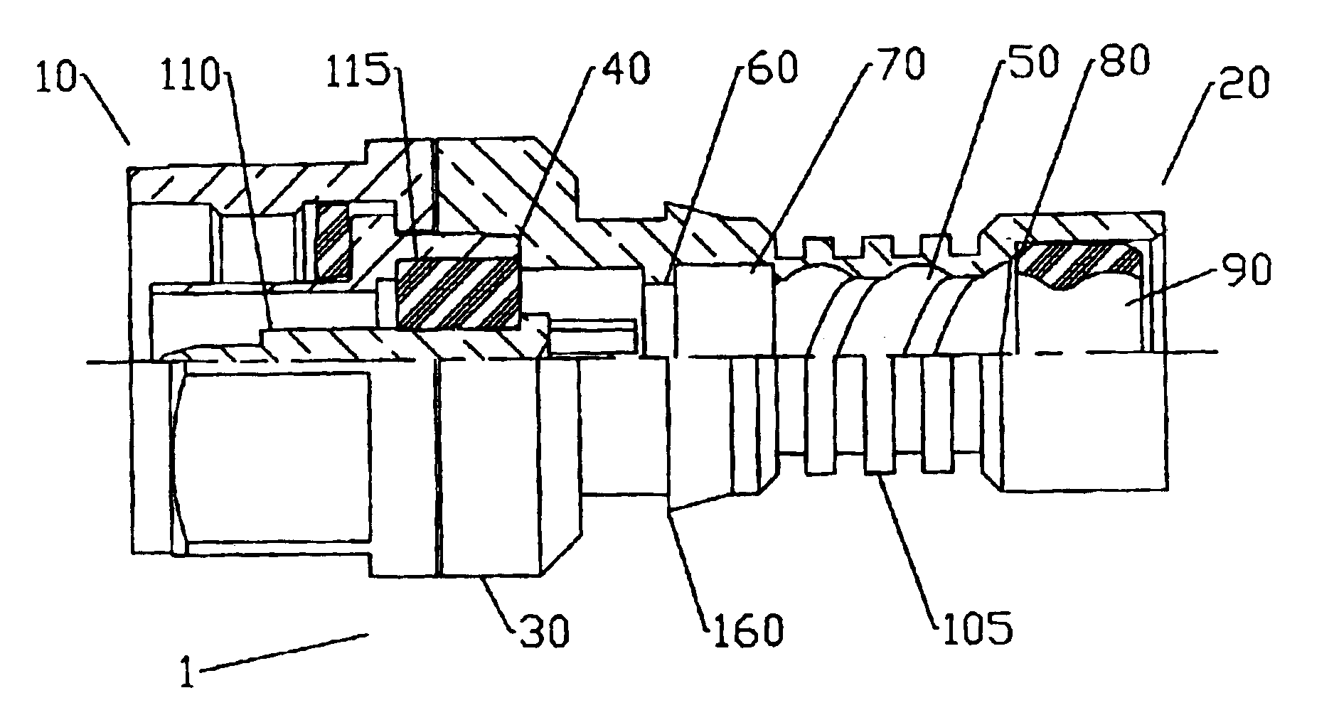
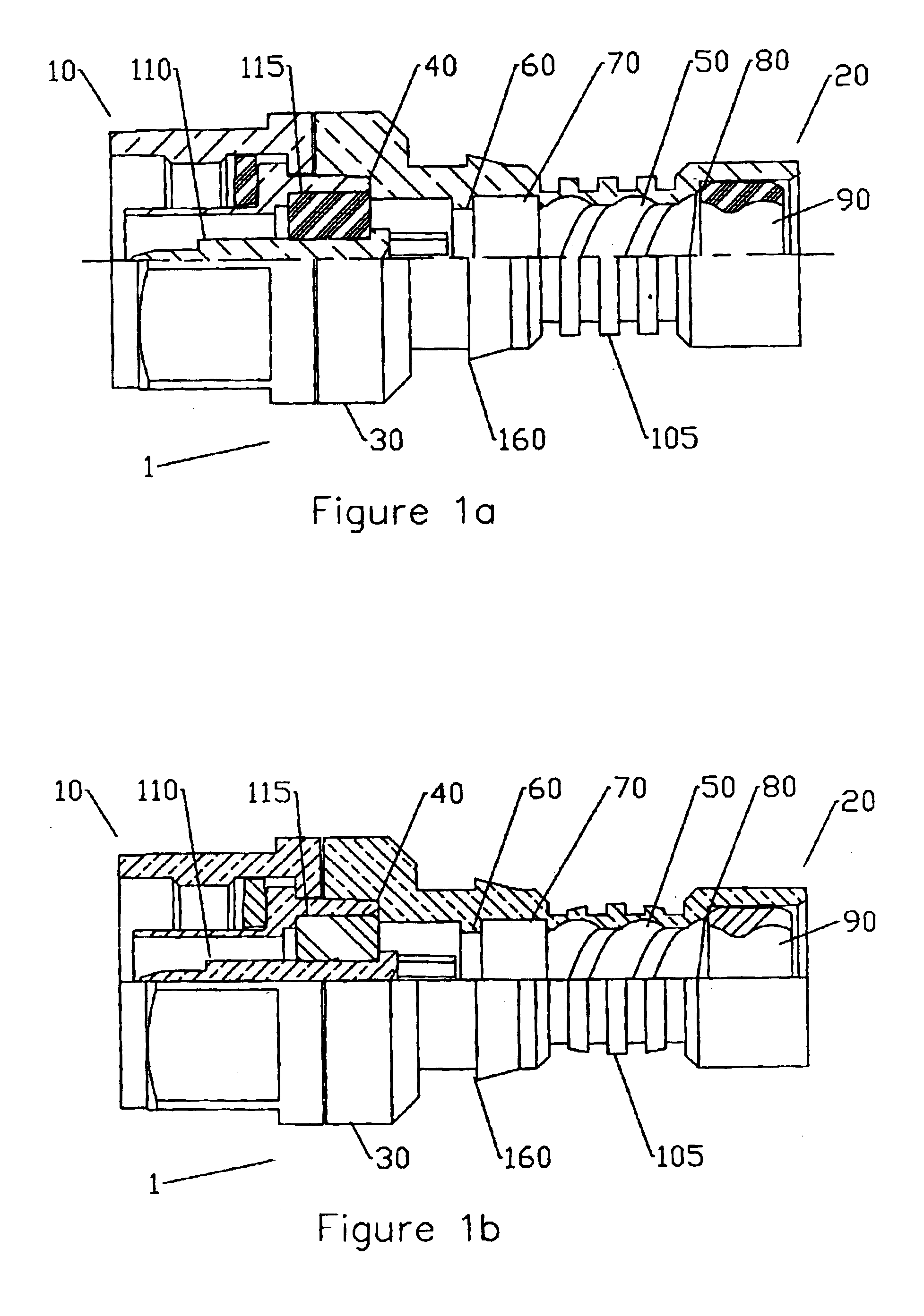
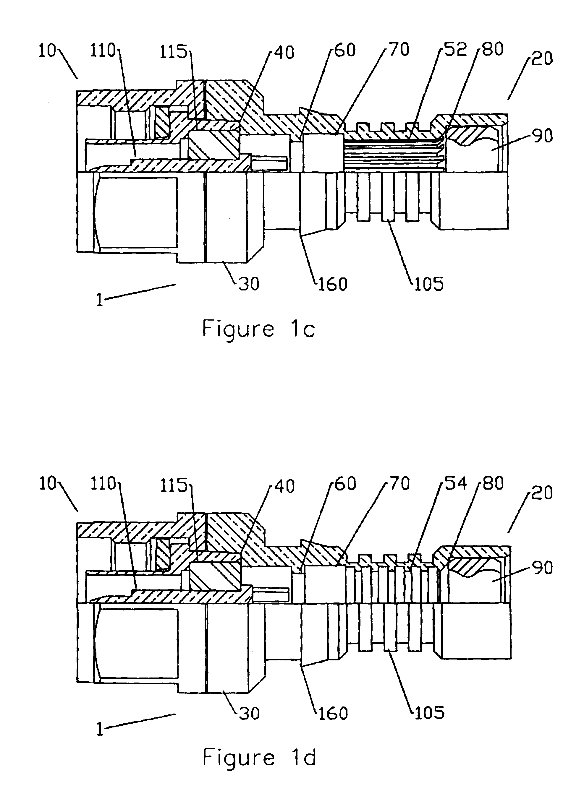
One embodiment of a crimp connector, for example a type N connector, is shown in FIG. 1a. The crimp connector 1 has a connector end 10 (FIG. 2) and a cable end 20 (FIG. 3). The specific form or connector interface of connector end 10 may depend on the coaxial cable diameter and or the application the crimp connector and selected coaxial cable is intended for. The connector end 10 of the crimp connector may be configured with a connector interface selected to mate with any type of connector mounted on a device or other cable using, for example, standard type F, BNC, SMA, DIN, UHF, CATV, EIA, or a proprietary connector interface configuration. Dimensions and or configuration of the crimp connector 1 at the connector end 10 that form the desired standardized connector type are known in the art. A connector end 10 in a type N connector interface configuration is shown in FIGS. 1a-1e, 2 and 3. A type F and or CATV connector interface configuration is shown in FIG. 11.

As shown in FIGS. 4a...


PUM


Abstract

A cable-connector system advantageously used with flexible, relatively small diameter coaxial cable and connectors, including a coaxial cable with a foam dielectric surrounding an inner conductor; and a tubular outer conductor surrounding the foam dielectric, the outer conductor being composed of aluminum or aluminum alloy and having helical corrugations; and a connector, having: a connector body having a hollow bore with internal perturbations keyed to the helical corrugations and arranged to retentively receive and secure the connector on the cable when the connector is screwed onto the cable with the corrugations engaging the perturbations; the connector body having a crimp section adapted to be compressed by a connector crimping tool; the crimp section configured such that when crimped, the crimp section deforms inwardly and distorts the cable outer conductor corrugations to prevent relative rotation between the cable and the connector body and interlock the connector and cable.

Description

BACKGROUND OF INVENTION1. Field of the InventionThe invention relates to an improved cable-connector system, and more particularly to a system comprising: 1) a low cost, high performance, water blocking aluminum cable as described in U.S. utility patent application Ser. No. 10 / 131,747 filed Apr. 24, 2002 also assigned to Andrew Corporation and hereby incorporated by reference in its entirety, and 2) a low cost, high performance water-blocking connector uniquely configured to mate with such low cost aluminum cable.As described in detail in the '747 application, no known cable product exists which met all four of the desired foam coaxial cable attributes: 1) low cost comparable to braided cable cost; 2) electrical properties including shielding effectiveness and intermodulation suppression comparable to that of solid tubular shielded cable; 3) mechanical properties, primarily flexibility, comparable to braided cable; and 4) water blockage comparable to annular corrugated cable.The uni...

Claims


Application Information

Patent Timeline
Patent Type & Authority Patents(United States)
IPC IPC(8): H01R9/05H01R13/52H01R13/646
CPCH01R9/0518H01R13/5205H01R2103/00H01R24/564
Inventor WLOS, JAMESKRABEC, JAMES
Owner ANDREW LLC
Why Eureka
Try Eureka