

Sealing method and apparatus for manufacturing high-performance gas discharge panel
a gas discharge panel and high-performance technology, applied in the manufacture of electric discharge tubes/lamps, electrode systems, cold cathode manufacturing, etc., can solve the problems of lcds consuming a small amount of electricity, crts are not suitable for large screen sizes, and the depth and weight increas
Inactive Publication Date: 2005-02-01
PANASONIC CORP
View PDF16 Cites 19 Cited by
- Summary
- Abstract
- Description
- Claims
- Application Information
AI Technical Summary
Benefits of technology
[0023](2) A container whose inside is under a pressure lower than the pressure inside the surrounding unit is used to reduce the pressure inside the surrounding unit.
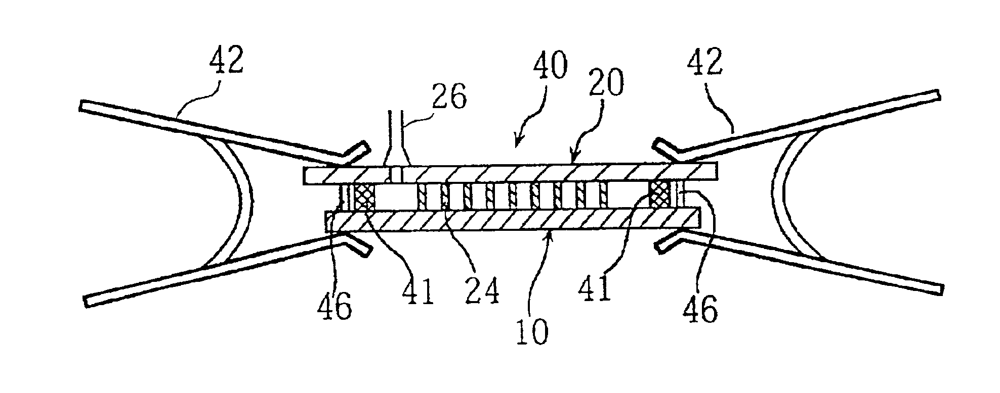
[0028]It is preferable that the sealing step is performed while the panels are pressurized by fastening tools pinching the panels so that the sealing process is more ensured. In this case, it is further preferable that an anti-deformation member is disposed at a position where the panels are pressurized by the fastening tools so as to prevent the panels from deforming by pressure by the fastening tools.
[0029]It is also preferable that the sealing step is performed while the surrounding unit is provided with anti-displacement means for preventing the relative displacement of the panels. It is further preferable that an anti-sealing-material-inflow member is disposed at the rim of a panel so as to prevent the sealing material from flowing into an inner area of the surrounding unit.
Problems solved by technology
However, the depth and weight increase as the screen size increases.
Therefore, CRTs are not suitable for large screen sizes exceeding 40 inch.
LCDs consume a small amount of electricity and operate on a low voltage.
However, producing a large LCD screen is technically difficult, and the viewing angles of LCDs are limited.
However, the PDPs manufactured with such a method have gaps between the barrier ribs and the front panel.
However, such fastening of the rim tends to generate a gap between the top of the barrier ribs and the front panel at the center by the action of a lever.
In addition, unequal gaps are often formed since the pressures given by the fastening tools are different.
In the PDPs manufactured through the sealing process with such gaps, crosstalks often occur when the PDPs are activated, or noises often occur between the barrier ribs and the panels due to vibration of the panels caused by the u discharge or the like.
However, in reality, it is difficult to bond the whole top of the barrier ribs with the front panel.
Accordingly, this technique is not sufficient to solve the problem of the pressure.
Especially, when there are variations of the barrier ribs in height on the back panel, many parts remain unattached.
When this happens, it is impossible to obtain sufficient resistance to pressure.
However, according to this method, more energy is required for the heating since the weight on the panels is also heated.
It is difficult to use this technique for the production of large-screen PDPs.
Method used
View moreImage
Smart ImageViewing Examples

Examples
embodiment 11
[0049]FIG. 19 shows the sealing process of
embodiment 12
[0050]FIGS. 20A, 20B, 20C, and 20D show the sealing process of
[0051]FIGS. 21A to 21F are partial front views showing specific shapes of the anti-deformation rib used in Embodiment 12.
embodiment 13
[0052]FIGS. 22A, 22B, and 22C show the process of bonding the top of the barrier ribs to the front panel by radiating a laser beam in
[0053]FIG. 23 is a perspective view showing a specific laser processing apparatus used in Embodiment 13.
[0054]FIG. 24 shows an example of the laser processing apparatus used in Embodiment 13.
Login to View More PUM
 Abstract
A method is provided to steadily produce a gas discharge panel, such as a PDP, in which a panel and the top of the barrier ribs are in intimate contact in entirety. First a surrounding unit for the gas discharge panel is formed, then a process for sealing the surrounding unit with a sealing material inserted between two panels at the rim is performed while pressure is adjusted so that pressure inside the surrounding unit is lower than pressure outside. With this construction, the panels constituting the surrounding unit are bonded together while they are pressurized from outside. As a result, a panel and the top of the barrier ribs on the other panel are bonded together while they are in intimate contact in entirety. To fully acquire these effects, it is preferable that the adjustment of pressure starts before the sealing material hardens. During, before, or after the sealing step, an energy such as laser beams or ultrasonic waves may be radiated onto the top of the barrier ribs to bond a panel and the top of the barrier ribs in entirety almost without a gap between them.
Description
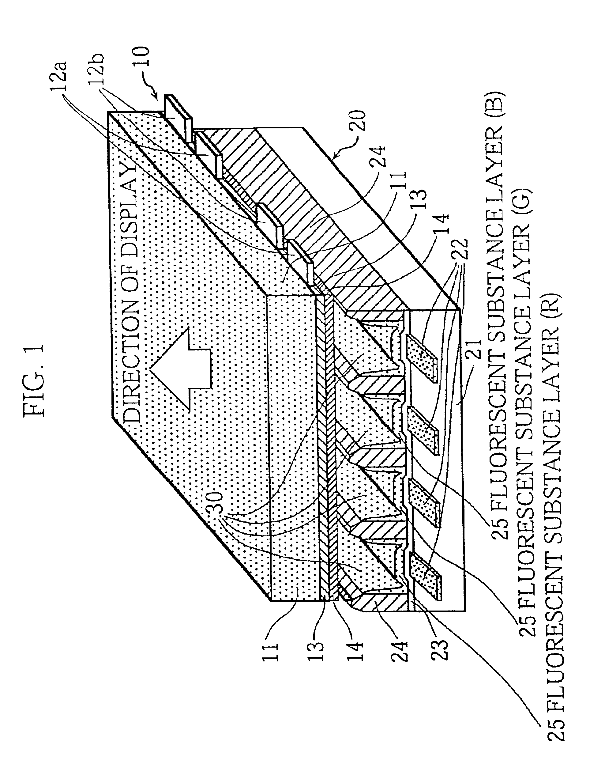
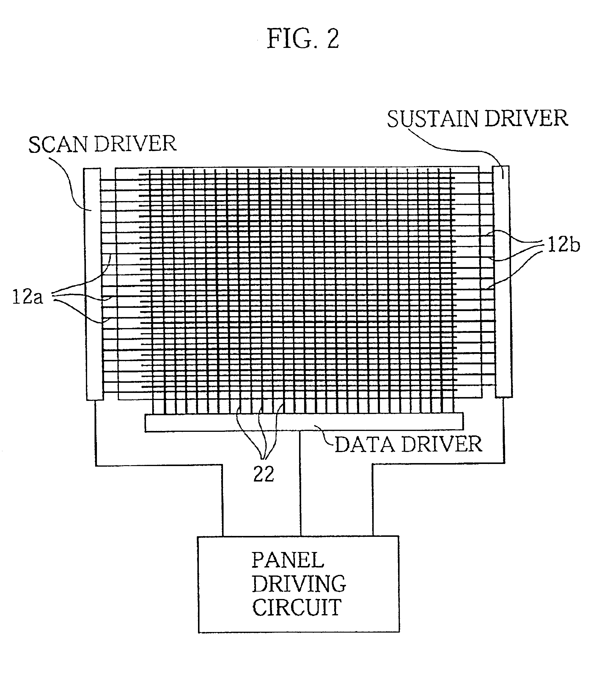
TECHNICAL FIELD[0002]This invention relates to a method for producing a gas discharge panel, more specifically to a process for bonding a front panel and a back panel.BACKGROUND ART[0003]Recently, as the demand for high-quality large-screen TVs such as high definition TVs has increased, displays suitable for such TVs, such as Cathode Ray Tube (CRT), Liquid Crystal Display (LCD), and Plasma Display Panel (PDP), have been developed.[0004]CRTs have been widely used as TV displays and excel in terms of resolution and picture quality. However, the depth and weight increase as the screen size increases. Therefore, CRTs are not suitable for large screen sizes exceeding 40 inch. LCDs consume a small amount of electricity and operate on a low voltage. However, producing a large LCD screen is technically difficult, and the viewing angles of LCDs are limited.[0005]On the other hand, it is possible to make a PDP with a large screen with a short depth, and 50-inch PDP products have already been ...
Claims
Login to View More Application Information
Patent Timeline
 IPC IPC(8): H01J17/49H01J9/26H01J9/24
CPCH01J9/385H01J9/395H01J9/265H01J9/261H01J11/10H01J2211/36
InventorSASAKI, YOSHIKINONOMURA, KINZOUHIBINO, JUNICHIYONEHARA, HIROYUKIYAMASHITA, KATUYOSHIKIRIHARA, NOBUYUKIOOTANI, KAZUOOOKAWA, MASAFUMI
OwnerPANASONIC CORP