System and method for end turn retention on a high speed generator rotor

a technology of end turn retention and high-speed generator, which is applied in the direction of dynamo-electric machines, magnetic circuit rotating parts, magnetic circuit shape/form/construction, etc., can solve the problems of mechanical breakdown of wires, inefficiencies in the operation of generators, and risk of generator failure, so as to simplify the wrapping process and improve the balance of rotors. the effect of robustness

Inactive Publication Date: 2005-02-01
HONEYWELL INT INC
View PDF4 Cites 23 Cited by
  • Summary
  • Abstract
  • Description
  • Claims
  • Application Information

AI Technical Summary

Benefits of technology

The present inventors have recognized that end turn supports employed on rotors can be designed to include flanges that provide support to the end turns to limit movement of the wires radially inward. By coupling these supports to end cap hats that limit movement of the wires radially outward, pressure is generated upon the wires in between the flanges and the end cap hats causing the wires to become packed and thereby more robust. At the same time, the coupling of the supports to the end cap hats forces the wires into precise desired locations, thereby improving rotor balance and robustness and simplifying the wrapping process.

Problems solved by technology

Improper balancing in particular can result not only in inefficiencies in the operation of the generators, but also in a risk of failure of the generators.
The centrifugal forces experienced by the rotors are sufficiently strong as to cause bending of the wires of these coils, which over time can result in mechanical breakdown of the wires.
Additionally, because the coils are assemblies of individual wires that can move to some extent with respect to one another and with respect to the remaining portions of the rotors, the coils constitute one of the significant potential sources of imbalance within the rotors.
The stresses and movement experienced by the wire coils are particularly problematic at the end turns of the coils, at which wires loop from first directions to second directions on the poles supporting the wires.
In order to guarantee robust wire coils and to minimize the amount of imbalance in the rotors that occurs due to the wire coils, the process of initially wrapping the wires of the coils onto the rotors is typically a time-intensive, expensive task.
To keep the wrapped coils to within specified tolerances, complicated tooling equipment and an involved process of utilizing shims to guarantee sufficient internal pressure among the wires of the coil are required.
Often, the wrapping process involves a significant amount of trial and error before all of the multiple coils on a multi-pole generator are properly configured to have the desired balancing and other characteristics.
The difficulty of the wrapping process is greatest at the end turns of the coil wires.

Method used


Image

  • System and method for end turn retention on a high speed generator rotor
  • System and method for end turn retention on a high speed generator rotor
  • System and method for end turn retention on a high speed generator rotor

Examples


Embodiment Construction

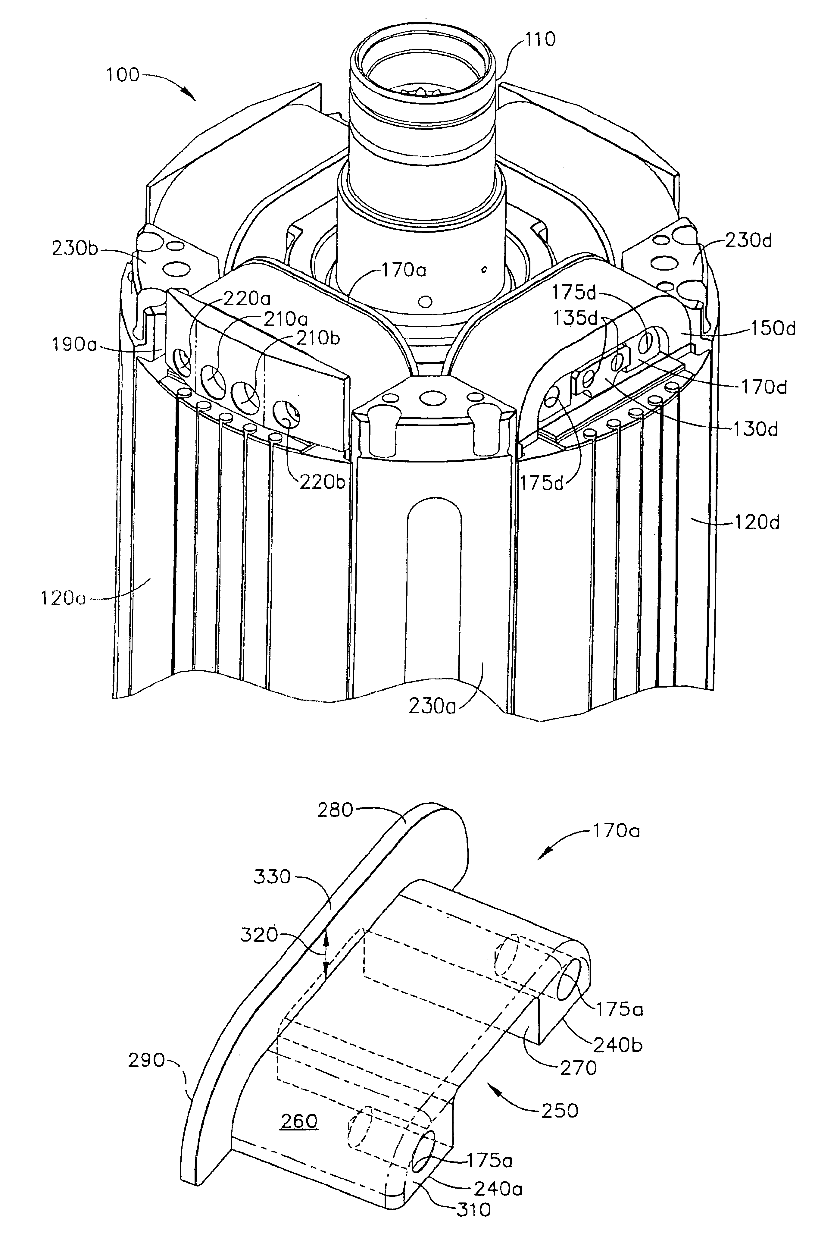
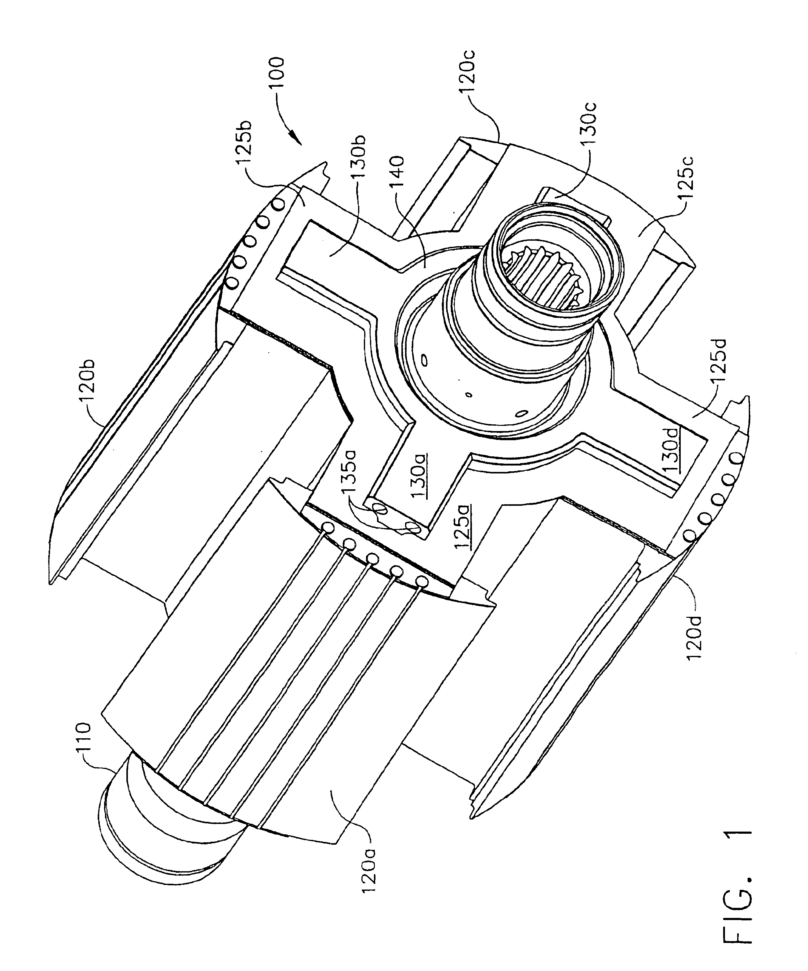
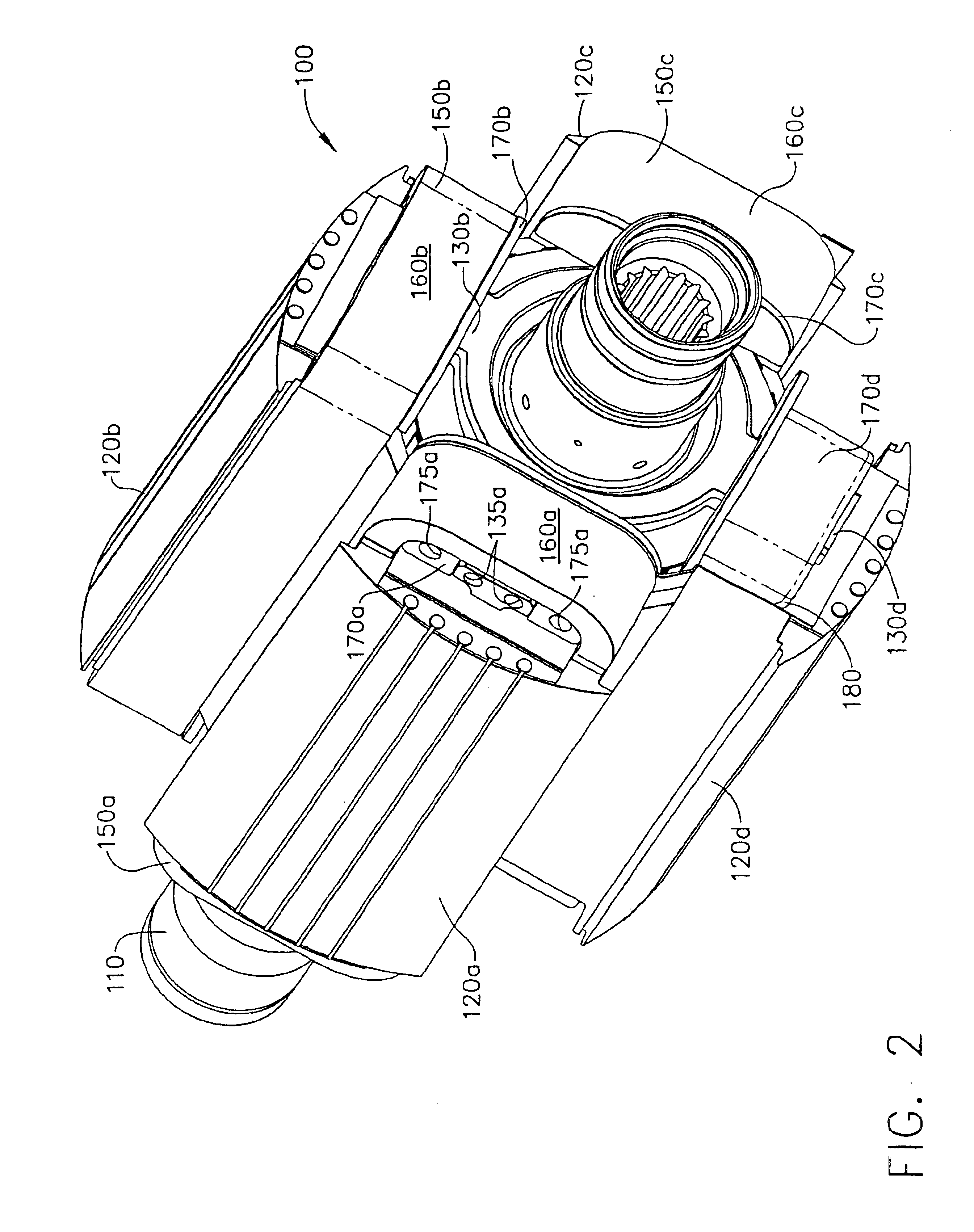
Referring to FIG. 1, components of an exemplary rotor 100 on which the present invention can be employed include a shaft 110 extending axially through the rotor, four poles 120a-d that extend radially away from the shaft 110, and four spokes 130a-d that extend radially away from the shaft 110 at a hub location 140. The spokes 130a-d are radially aligned with, and coupled to, end faces 125a-d of the poles 120a-d, respectively. As discussed further below, each of the spokes 130a-d respectively includes one or more threaded holes 135a-d (only holes 135a are shown in FIG. 1). The rotor 100 presently shown is designed for implementation in high speed generators such as those commonly employed in aircraft. Consequently, the components of the rotor 100 are typically manufactured from high-strength materials. For example, the poles 120a-d can be formed from steel, while the shaft 110 and the spokes 130a-d can be formed from steel, titanium or high-strength aluminum. It will be appreciated, ...


PUM


Abstract

A new improved system and method for end turn retention for wires on a generator rotor for use in high speed applications such as in aircraft applications. The rotor includes a shaft, spokes, supports, and wire winding coils, and at least one cap device. The spokes extend radially outwardly from the shaft, and each support is positioned on an associated spoke. Each coil wraps around an associated support and spoke. Each cap device is coupled to an end of its associated spoke to prevent the windings from moving radially outwardly while the rotor spins. Each support is coupled to an associated cap device, and includes at its radially inward edge a flange protruding away from the respective spoke. Because of the flange and the cap device, slack of the wire coil between the flange and the associated cap is taken up.

Description

FIELD OF THE INVENTIONThe present invention relates to high speed generators and, more particularly, to systems and methods for fastening wire coils to the rotors of such generators.BACKGROUND OF THE INVENTIONGenerator systems that are installed in aircraft may include three separate brushless generators, namely, a permanent magnet generator (PMG), an exciter, and a main generator. The PMG includes permanent magnets on its rotor. When the PMG rotates, AC currents are induced in stator windings of the PMG. These AC currents are typically fed to a regulator or a control device, which in turn outputs a DC current. This DC current next is provided to stator windings of the exciter. As the rotor of the exciter rotates, three phases of AC current are typically induced in the rotor windings. Rectifier circuits that rotate with the rotor of the exciter rectify this three-phase AC current, and the resulting DC currents are provided to the rotor windings of the main generator. Finally, as the...

Claims


Application Information

Patent Timeline
Patent Type & Authority Patents(United States)
IPC IPC(8): H02K3/52H02K1/22H02K3/46H02K1/24
CPCH02K3/527H02K1/24
Inventor TORNQUIST, GERALD E.MCDOWALL, GREGOR J. S.XU, MINGZHOUDOHERTY, KIERAN P. J.LENGEL, JIM
Owner HONEYWELL INT INC
Why Eureka
Try Eureka