Borehole logging apparatus for deep well drilling

a drilling apparatus and deep well technology, applied in the field of deep well drilling drilling borehole logging apparatus, can solve the problems of energy and time consumption, requiring a correspondingly long interruption of drilling operation, etc., and achieve the effect of long service li

Inactive Publication Date: 2005-02-01
PRECISION ENERGY SERVICES
View PDF8 Cites 24 Cited by
  • Summary
  • Abstract
  • Description
  • Claims
  • Application Information

AI Technical Summary

Benefits of technology

[0005]It is an object of the present invention to provide a borehole logging apparatus of the type initially referred to which enables the partial currents fed to the signal transmitter and the bypass o

Problems solved by technology

Each conversion necessitates however the removal of the borehole logging apparatus, which involves considerable expenditure o

Method used


Image

  • Borehole logging apparatus for deep well drilling
  • Borehole logging apparatus for deep well drilling

Examples


Embodiment Construction

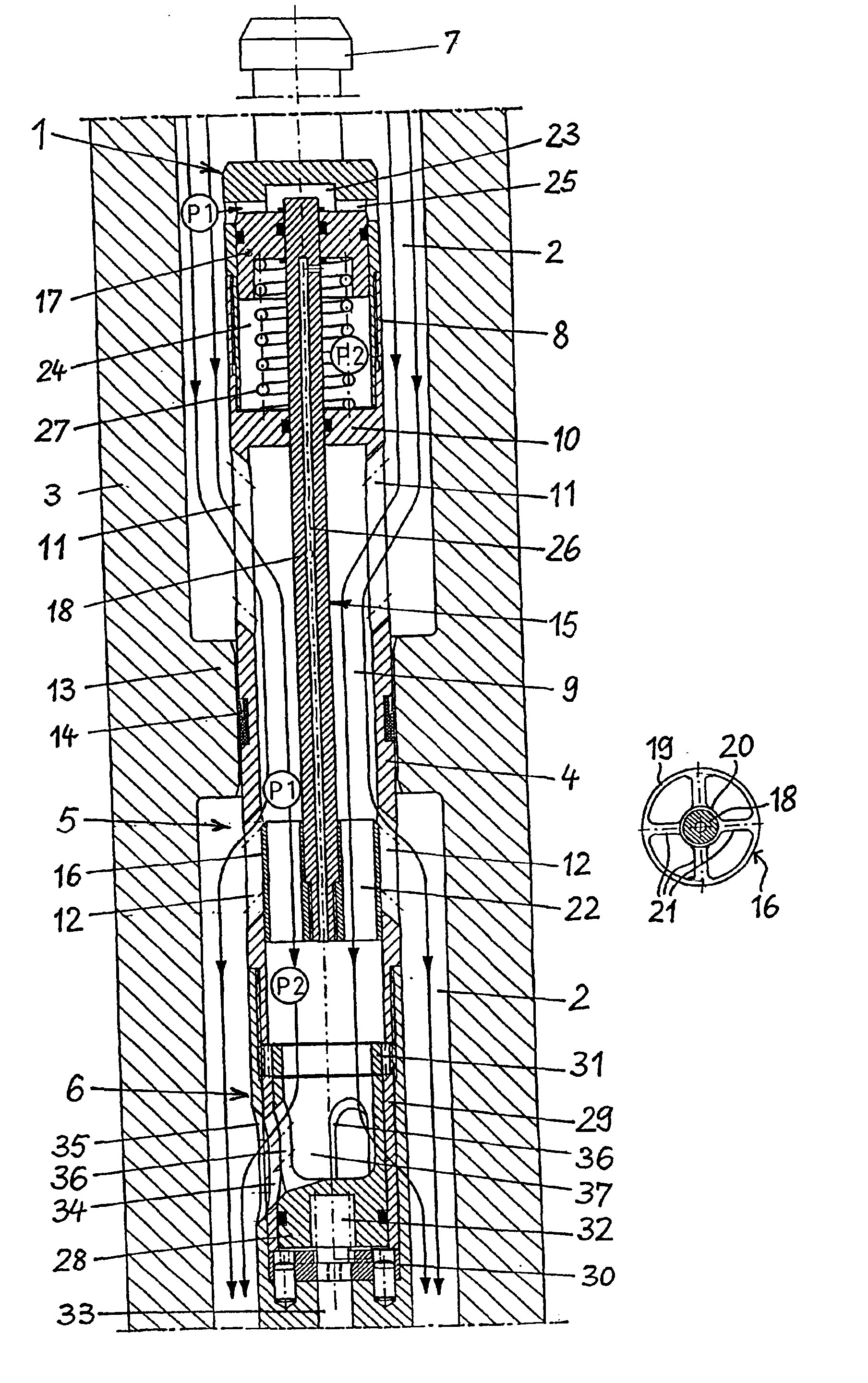
the invention with flow regulator and hydromechanical signal transmitter; and

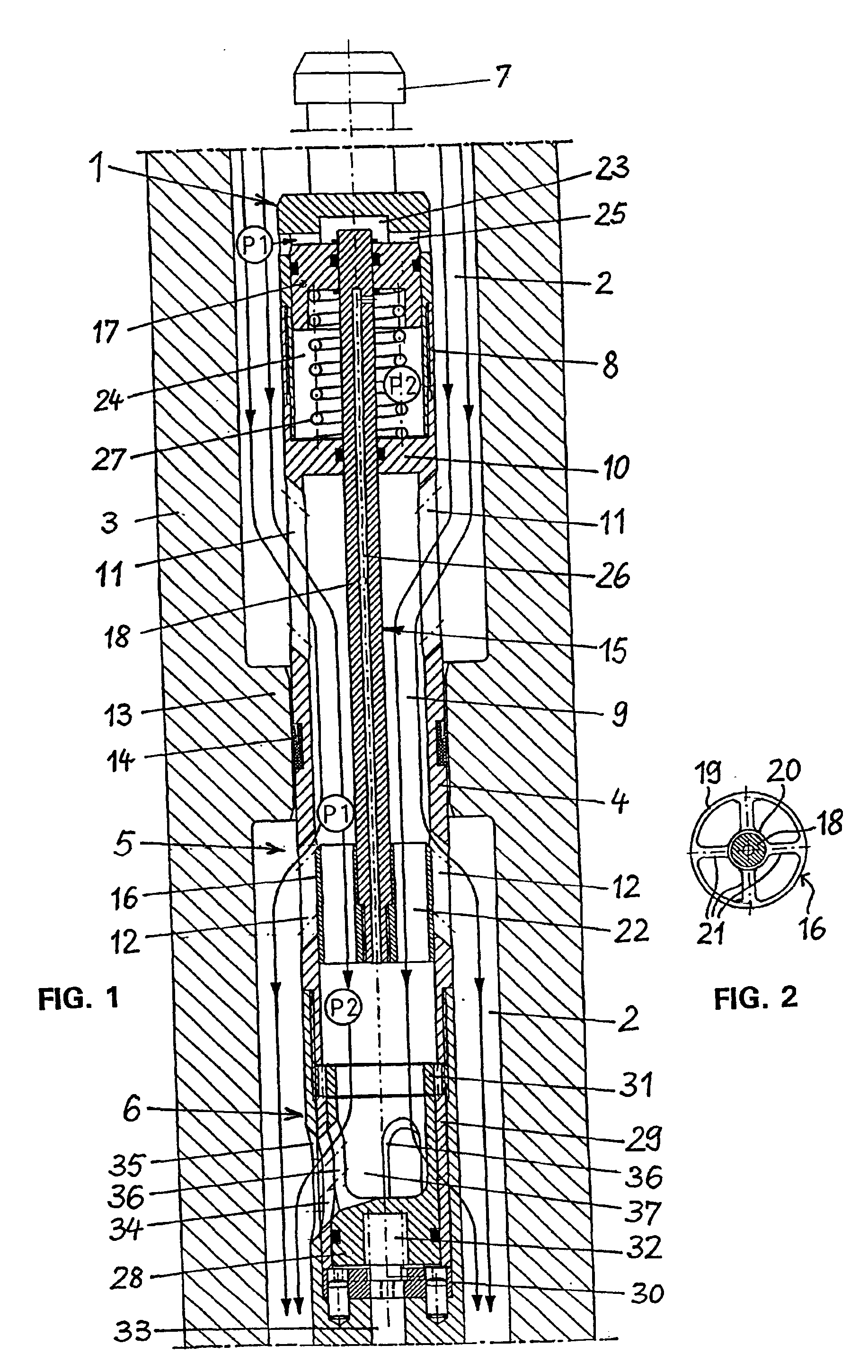
[0012]FIG. 2 is a cross-sectional view of the throttling section of the control piston of the borehole logging apparatus of FIG. 1.

DESCRIPTION OF THE PREFERRED EMBODIMENT

[0013]FIG. 1 shows the upper section of a borehole logging apparatus 1 arranged in the drilling fluid conduit 2 of a drill collar 3 of a drill string for deep well drilling. The borehole logging apparatus 1 comprises a housing 4 composed of several housing parts bolted together and having the form of an elongated cylindrical rod. Arranged in the section of the housing 4 shown are a flow regulator 5 and a hydromechanical signal transmitter 6, while further units such as the drive of the signal transmitter 6, a measuring probe, a measuring transducer, a signal generator and an energy storage are arranged in the lower section of the housing 4, not shown. Provided at the upper end of the housing 4 is a catch hook 7 by which the borehole logging...


PUM


Abstract

The invention is directed to a borehole logging apparatus for deep well drilling, with a signal transmitter for transmitting measured data obtained while drilling from a borehole through the drilling fluid to the earth's surface, and with an elongated housing which is adapted for insertion in the drilling fluid conduit of a drill string. Accommodated in the housing is a flow regulator with a control piston, which controls the cross-section of opening of a bypass opening in response to the pressure differential generated by a flow restrictor and in response to the force of a spring in such manner that the part of the drilling fluid current fed to the signal transmitter through the flow restrictor is maintained substantially constant, and the remaining excess drilling fluid current is routed to the drilling fluid conduit via the bypass opening.

Description

BACKGROUND OF THE INVENTION[0002]This invention relates to a borehole logging apparatus for deep well drilling, with a device for transmitting measured data obtained while drilling from a borehole through the drilling fluid to the earth's surface, with an elongated housing which is adapted for insertion in the drilling fluid conduit of a drill string, includes at its influx end an entrance opening leading into a central housing conduit and has, downstream from the entrance opening, a sealing ring effecting a seal against the drill string, which further includes a bypass opening arranged downstream from the sealing ring and leading from the central housing conduit into the drilling fluid conduit of the drill string, and, downstream from the bypass opening, has a passageway connecting the central housing conduit with the drilling fluid conduit of the drill string, said passageway being adapted to be throttled at least in part by a controllable closure element of a hydromechanical sign...

Claims


Application Information

Patent Timeline
IPC IPC(8): E21B47/18E21B47/12
CPCE21B47/187E21B47/18E21B47/24
Inventor WINNACKER, HELMUT
Owner PRECISION ENERGY SERVICES
Why Eureka
Try Eureka