Disk array system and a method for controlling the disk array system

a disk array and disk array technology, applied in the field of disk array technology, can solve the problems of no improvement in the system performance of shared-bus-connected disk arrays, low i/o performance, and low performance of i/o arrays, and achieve the effect of improving the usage status of a connection path and high throughpu

Inactive Publication Date: 2005-02-01
HITACHI LTD
View PDF10 Cites 21 Cited by
  • Summary
  • Abstract
  • Description
  • Claims
  • Application Information

AI Technical Summary

Benefits of technology

A first object of the present invention is to provide a disk array system with a high throughput of transferring data between a host interface unit, a disk interface unit, and a shared memory without increasing the number of connection paths more than necessary. This object is accomplished by improving the usage status of a connection path between switching means and the shared memory unit.
According to the present invention, it is possible to make a connection path between a host interface unit and the switch unit, between a disk interface unit and the switch unit, and a connection path between the switch unit and a shared memory unit to have different transfer throughputs. Thus, a disk array system that can easily support a plurality of different host I / F channels can be provided.

Problems solved by technology

Although magnetic disk subsystems are widely employed as a secondary storage device for a computer, their I / O performance is always lower than the I / O performance of a main storage by three to four orders of magnitude.
In the case of the common bus, both the bus width and the operating frequency are almost approaching their limits in recent years, so that there has been no improvement in the system performance of the shared-bus-connected disk array.
On contrast therewith, in the shared-bus-connected disk array, an improvement in the system performance is becoming difficult due to the bottleneck in the performance of the common bus, so that the shared-bus-connected disk array cannot satisfy the market requirements.
However, even in the starnet connection disk array, the number of the connection paths is actually limited due to the constraints of installation.
Further, even if paths for one-to-one connection are employed between the respective interface units and the switch, and between the switch and the respective shared memory units, there exists a limit to the operating frequency of the paths.
Thus, an improvement in the performance of a single connection path is also limited.
Consequently, there develop memory connection paths that do not operate simultaneously at a given time, which has become a factor in limiting the throughput of the internal paths in the starnet connection disk array.
Thus, the effect of improving the maximum throughput of the system would be low.
Hence, the challenge is that the paths connecting the host interface units and the disk interface units to the switch and the memory connection paths connecting the switch to the shared memory units can be operated with their transfer throughputs being different to each other.

Method used


Image

  • Disk array system and a method for controlling the disk array system
  • Disk array system and a method for controlling the disk array system
  • Disk array system and a method for controlling the disk array system

Examples


Embodiment Construction

An embodiment of the present invention will be described in detail with reference to the appended drawings.

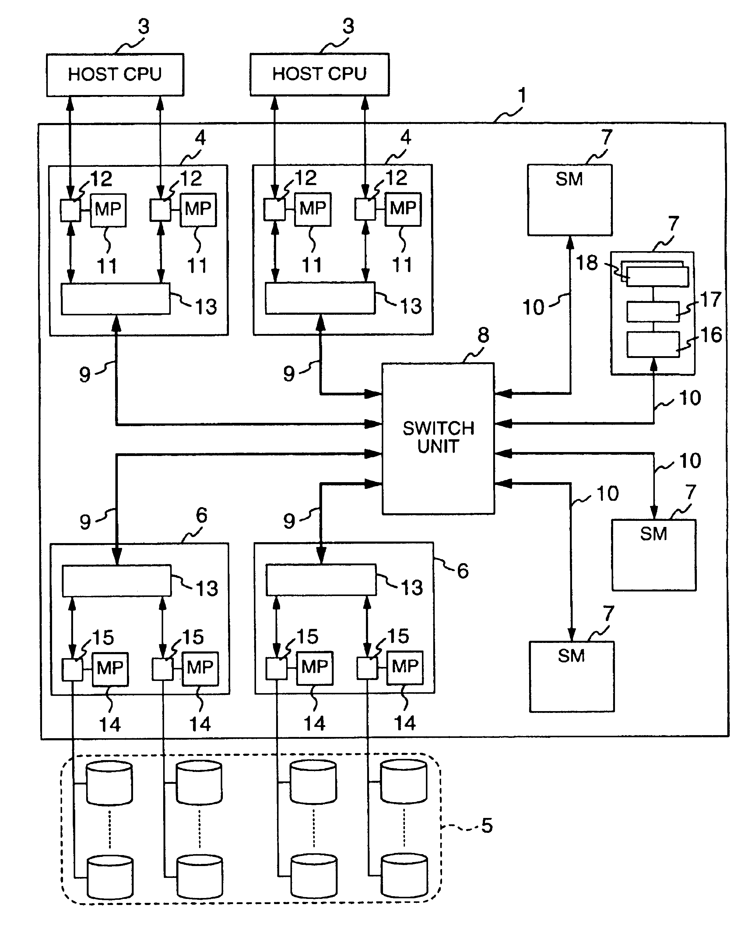
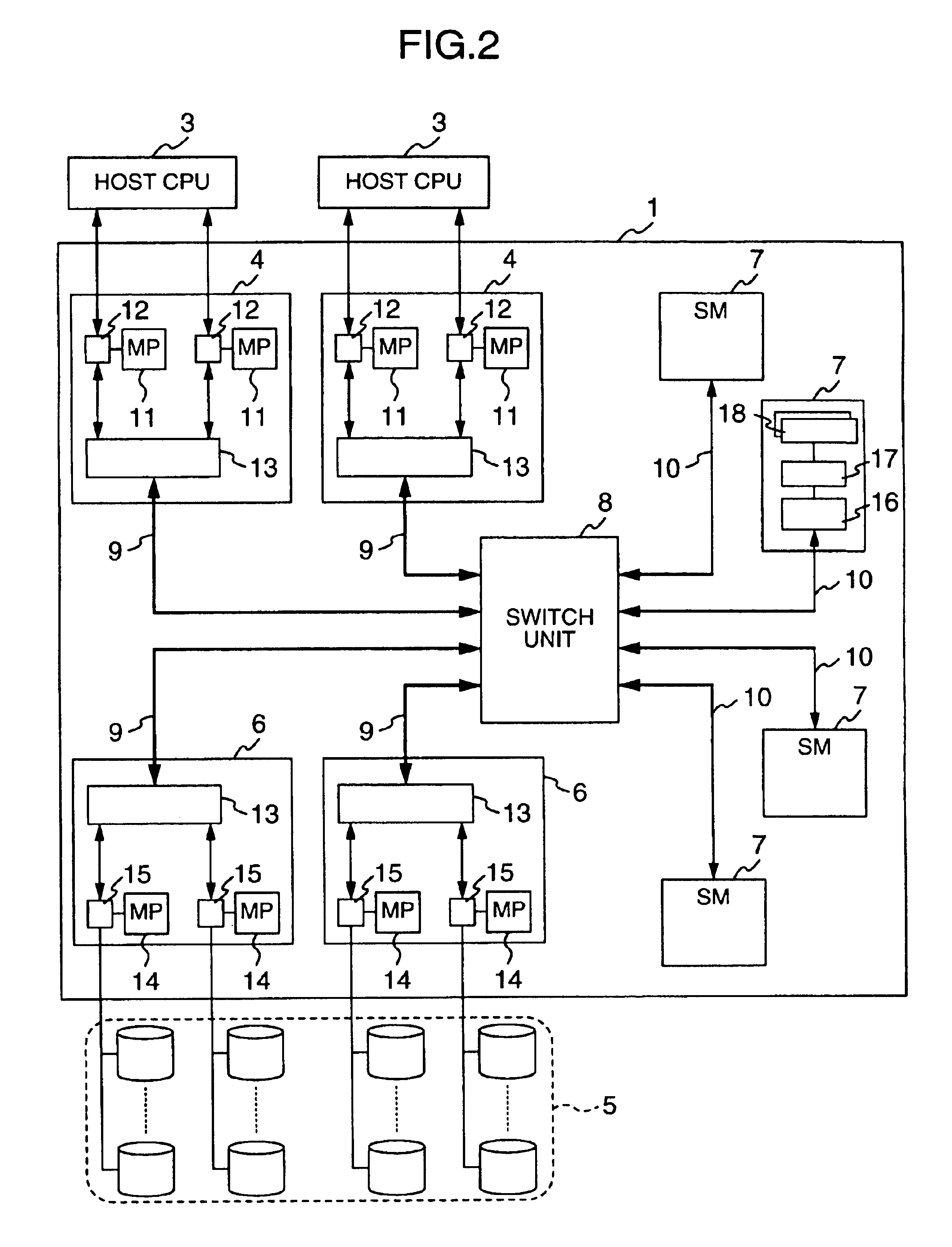
FIG. 2 is a conceptual diagram showing a configuration of a disk array system including a disk array control device that carries out a control method according to an embodiment of the present invention.

The disk array system according to this embodiment comprises a plurality of disk drives 5 that constitutes a disk array and a disk array control device 1 for controlling these drives.

The disk array control device 1 comprises host interface units 4 connected to a plurality of host computers (host CPUs 3), disk interface units 6 connected to a plurality of the disk drives 5, a switch unit 8, and shared memory units 7 for temporarily storing control information on the system and data to be written into the disk drives 5.

The respective host interface units 4, respective disk interface units 6 are interconnected to the switch unit 8 by a plurality of separate paths 9, which will be he...


PUM


Abstract

In a disk array system of the present invention, each host or disk interface unit is connected to each shared memory unit through a switch unit. The switch unit includes the number of packet buffers greater than the number of the host or disk interface units connected thereto, and can always hold the number of access requests greater than the number of the host or disk interface units. The disk array system uses the packet buffers to compensate for a transfer rate difference between the host interface units and the shared memory units, thereby allowing connection of the host interface units having different performance. The disk array system improves the efficiency of usage of internal paths without increasing the number of I / O ports of the switch unit. The system throughput is thereby improved, and the support for host I / Fs having different performance is thereby facilitated.

Description

CROSS-REFERENCE TO RELATED APPLICATIONThe basic foreign Application filed on Sep. 6, 2001, No. 2001-270940 in Japan is hereby incorporated by reference.FIELD OF THE INVENTIONThe present invention relates to a disk array technique. More specifically, the invention relates to a technique that is effective in being applied to configuration of and control over an access path for a shared memory in a disk array control device that constitutes a disk subsystem or disk array system.BACKGROUND OF THE INVENTIONAlthough magnetic disk subsystems are widely employed as a secondary storage device for a computer, their I / O performance is always lower than the I / O performance of a main storage by three to four orders of magnitude. Thus, efforts have long been made to reduce this difference. As a method of improving the I / O performance of the subsystem, there is known a disk array system in which a plurality of magnetic disk drives are operated in parallel to distribute data for storage in these pl...

Claims


Application Information

Patent Timeline
Patent Type & Authority Patents(United States)
IPC IPC(8): G06F12/00G06F13/14G06F3/06G06F3/00
CPCG06F3/0613G06F3/0689G06F3/0656
Inventor INOUE, MITSURUFUJIMOTO, KAZUHISA
Owner HITACHI LTD
Why Eureka
Try Eureka