
Component-placing apparatus

a technology of component placement and component, which is applied in the direction of metal working apparatus, manufacturing tools, transportation and packaging, etc., can solve the problems of large size of rotary motor, large inertia ineffective thrust force generation of voice coil motor, etc., and achieve the effect of small siz

Inactive Publication Date: 2005-02-08
MURATA MFG CO LTD
View PDF8 Cites 30 Cited by
  • Summary
  • Abstract
  • Description
  • Claims
  • Application Information

AI Technical Summary

Benefits of technology

Enables precise, high-speed placement of components with reduced power consumption and minimized tilting of the suction nozzle, allowing for efficient and accurate pick-and-place operations.

Problems solved by technology

In the former proposal, when the voice coil motor is used as the cylindrical linear motor, since the shaft extends through the center of the voice coil motor, the central part of the motor cannot be used as a core; hence, the voice coil motor does not effectively generate a thrust force.
Accordingly, the size of the voice coil motor must unavoidably be large.
Also, the rotary motor is rotated together with a yoke and a casing of the voice coil motor, thereby causing problems of large inertia and large size of the rotary motor.
In addition, when a moving coil of the voice coil motor rotates together with the shaft, feeding the moving coil with current is difficult.
In the latter proposal, since the hollow pressure shaft extends through the center of the voice coil motor, the central part of the motor cannot be used as a core; hence the voice coil motor does not effectively generate a thrust force, thereby requiring the voice coil motor to be large.
In addition, since a moving coil of the voice coil motor rotates together with the shaft, feeding the moving coil with current is difficult.

Method used


Image

  • Component-placing apparatus
  • Component-placing apparatus
  • Component-placing apparatus

Examples


Embodiment Construction

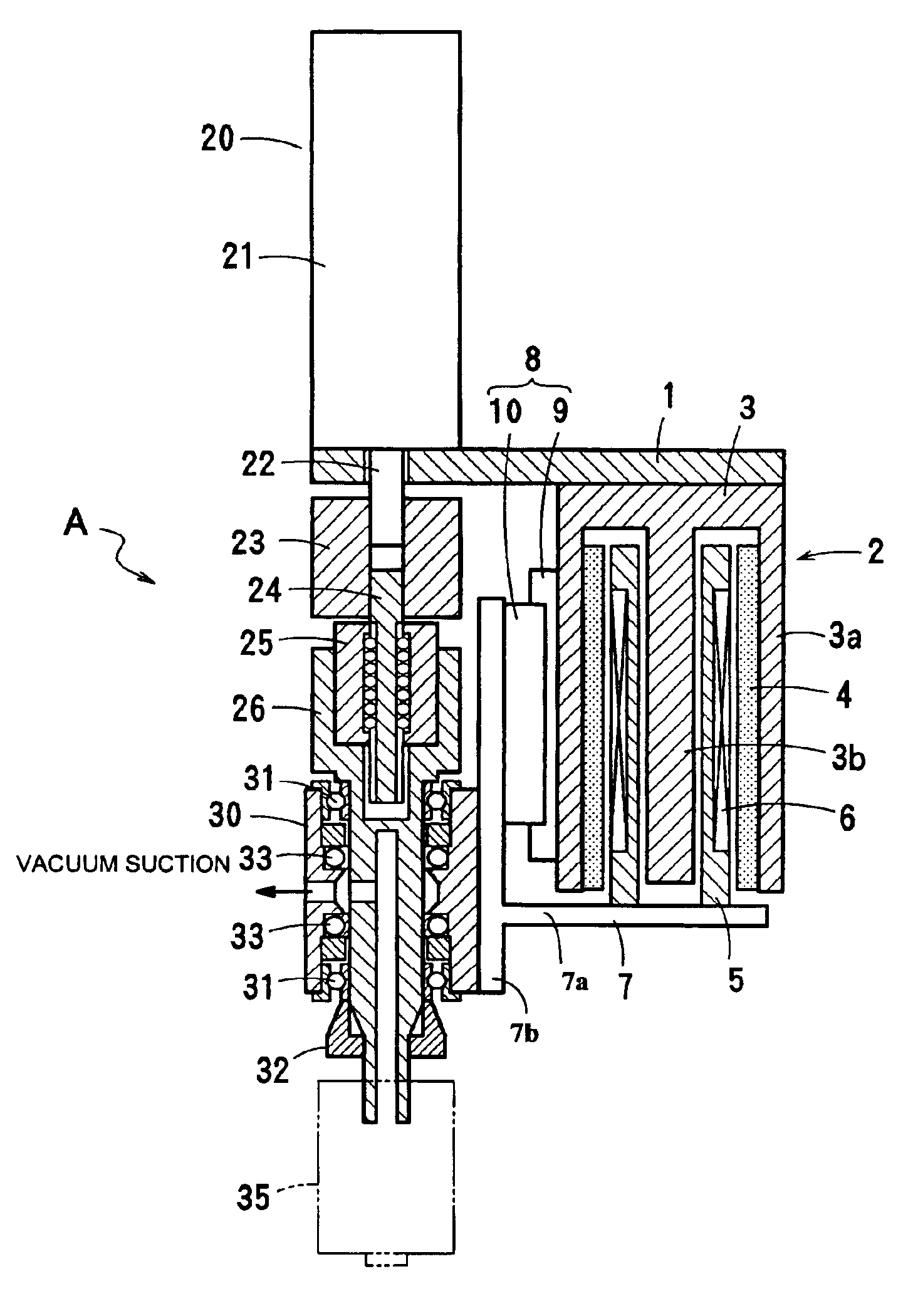
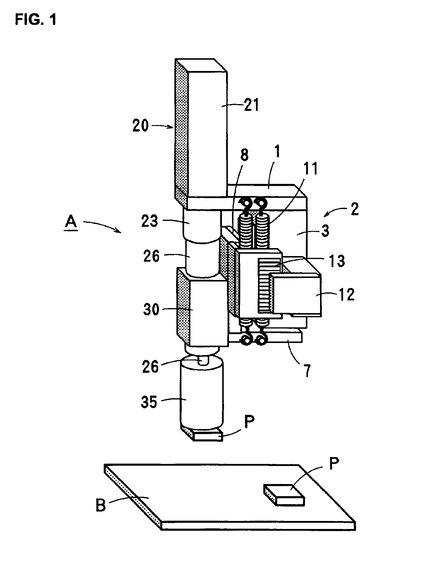
FIGS. 1 to 4 show a component-placing head (i.e., a component-placing apparatus) according to an embodiment of the present invention. Here, an electronic component P and a board B are referred to as a component and a fixing surface, respectively.

A component-placing head A according to the embodiment includes a supporting plate 1 fixed to a head of an X-Y robot or the like, a voice coil motor 2 as an example of a linear actuator having a stator (yoke) 3 fixed on the under surface of the supporting plate 1, and a servomotor 20 as an example of a rotary actuator having a stator 21 fixed on the upper surface of the supporting plate 1.

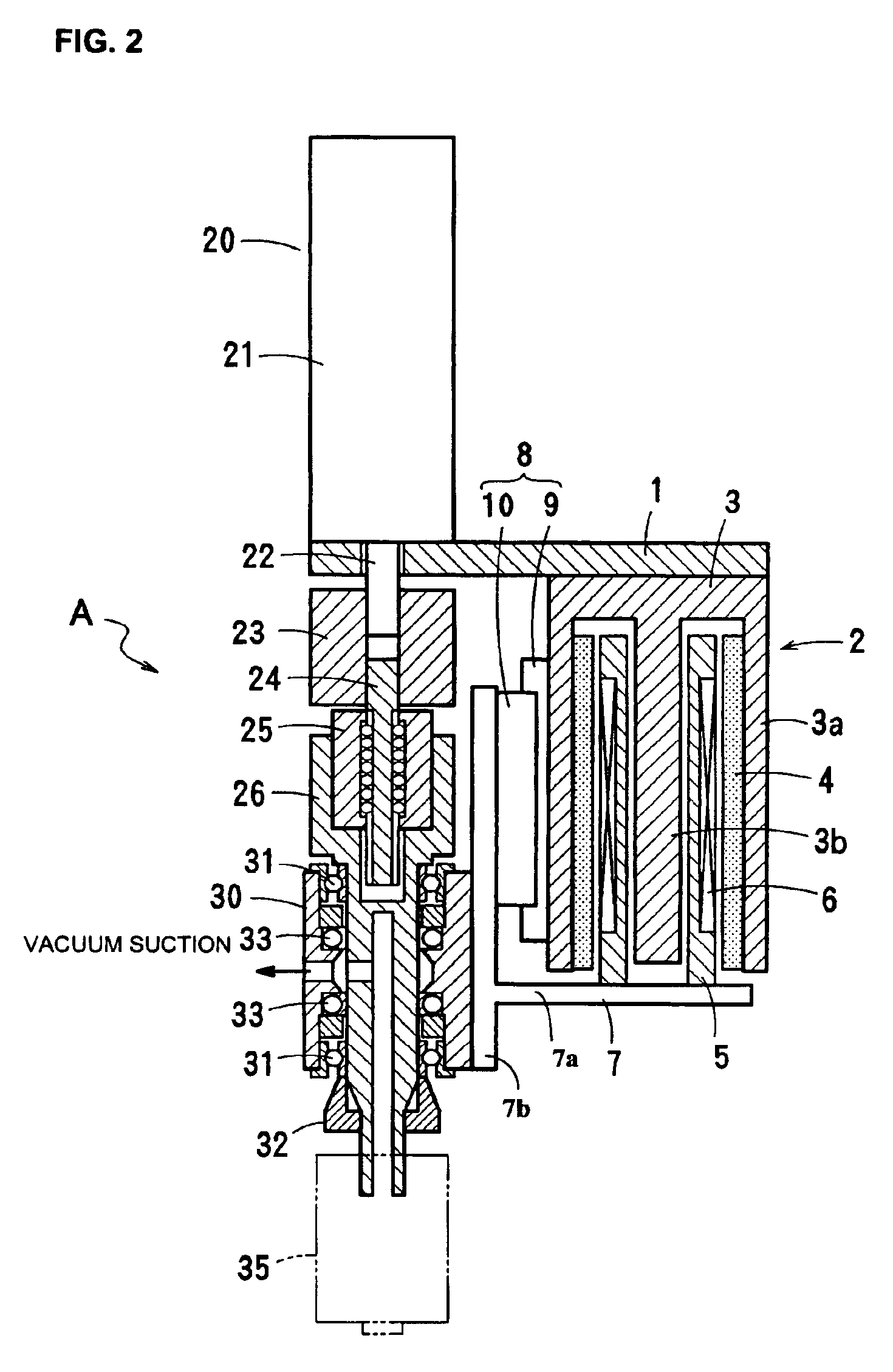
As shown in FIG. 2, the voice coil motor 2 is fixed on the lower surface of the supporting plate 1 and formed by the yoke 3 having an outer yoke 3a and a center yoke 3b, a magnet 4 fixed on the inner surface of the outer yoke 3a, a bobbin 5 inserted in the yoke 3 so as to be vertically movable, a coil 6 wound around the bobbin 5, and so forth. The coil 6 li...


PUM

PropertyMeasurementUnit
suctionaaaaaaaaaa
spring forceaaaaaaaaaa
forceaaaaaaaaaa

Abstract

A component-placing apparatus for driving a nozzle in the rotational and vertical directions for applying suction to a component includes a rotary actuator and a linear actuator having a stator connected to a stator of the rotary actuator such that these stators are immovable relative to each other. A spline shaft is connected to a rotating shaft of the rotary actuator, and a nozzle connecting shaft having a suction nozzle disposed at the bottom thereof is engaged with the spline shaft and is allowed to move only rectilinearly. A hollow holder encircling the nozzle connecting shaft with rotary bearings being interposed therebetween is connected to a mover of the linear actuator, and the hollow holder is engaged with the stator of the linear actuator with a linear guide being interposed therebetween.

Description

BACKGROUND OF THE INVENTION1. Field of the InventionThe present invention relates to a component-placing apparatus having a suction head for mounting an electronic component on a board or the like, or for assembling electronic components.2. Description of the Related ArtHitherto, a component-placing apparatus having a suction head has been used for mounting an electronic component such as a semiconductor chip and / or a piezoelectric component on a board such as a printed circuit board.As an example of such a component-placing apparatus, as disclosed in Japanese Unexamined Patent Application Publication No. 5-82998, a nozzle head has been proposed in which a rotary motor for rotating a nozzle for applying suction to an electronic component and a cylindrical linear motor for vertically moving the nozzle, are disposed coaxially with the nozzle, such that moving parts of these motors rotate or move vertically while being integral with the nozzle.Also, as disclosed in Japanese Unexamined ...

Claims


Application Information

Patent Timeline
Patent Type & Authority Patents(United States)
IPC IPC(8): H05K13/04B23P21/00
CPCH05K13/0408Y10T29/53178H05K13/0409H05K13/0413B23P21/00
Inventor HIRATA, ATSUHIKO
Owner MURATA MFG CO LTD
Learn More