
Variable strength stent

a stent and variable strength technology, applied in the field of expandable endoprosthesis devices, can solve the problems of limited expandability range, increased manufacturing cost, and limited expansion of certain prior art stents, and achieve the effects of facilitating delivery, enhancing longitudinal flexibility and configuration, and facilitating delivery

Inactive Publication Date: 2005-02-08
ABBOTT CARDIOVASCULAR
View PDF85 Cites 130 Cited by
  • Summary
  • Abstract
  • Description
  • Claims
  • Application Information

AI Technical Summary

Benefits of technology

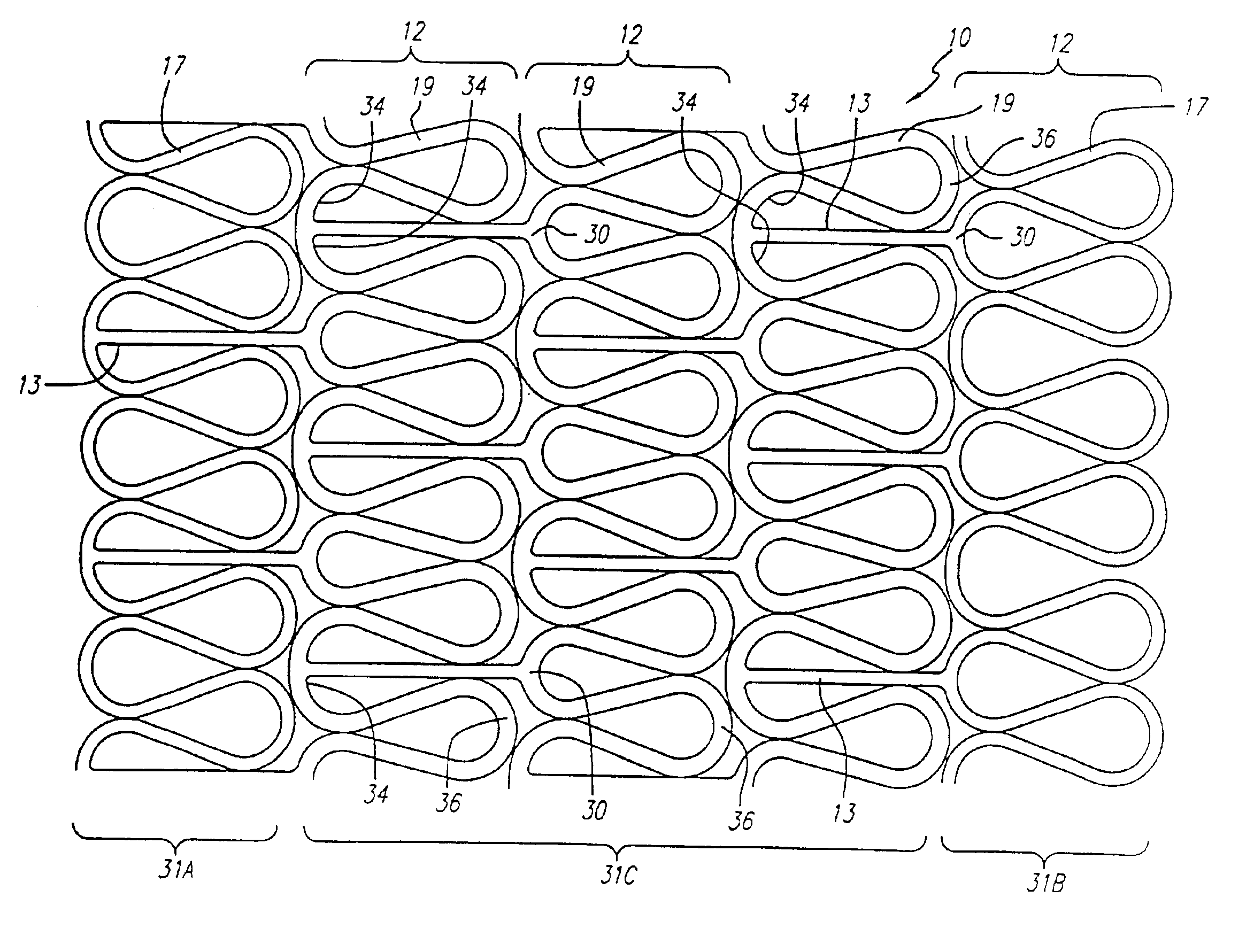
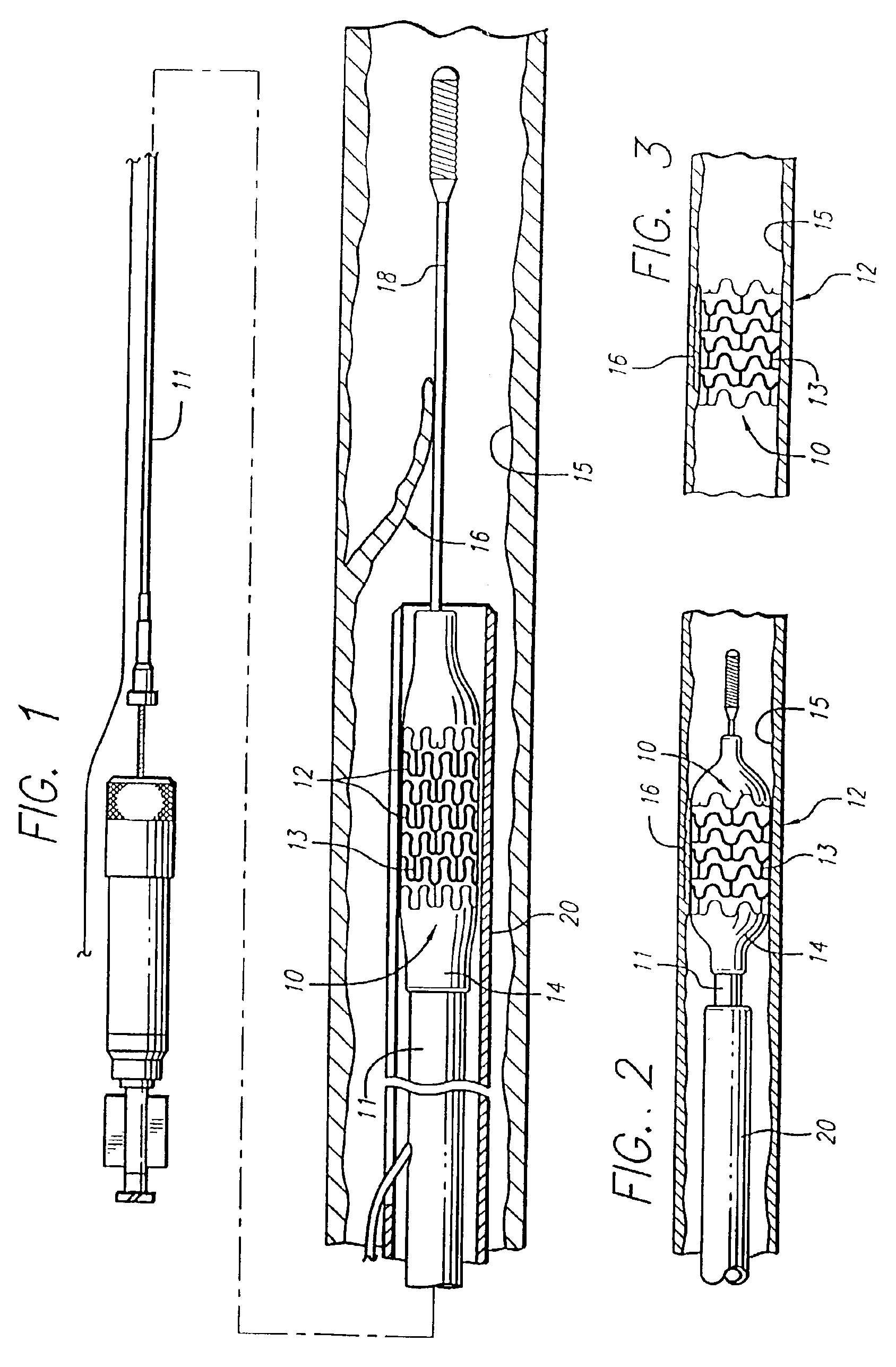
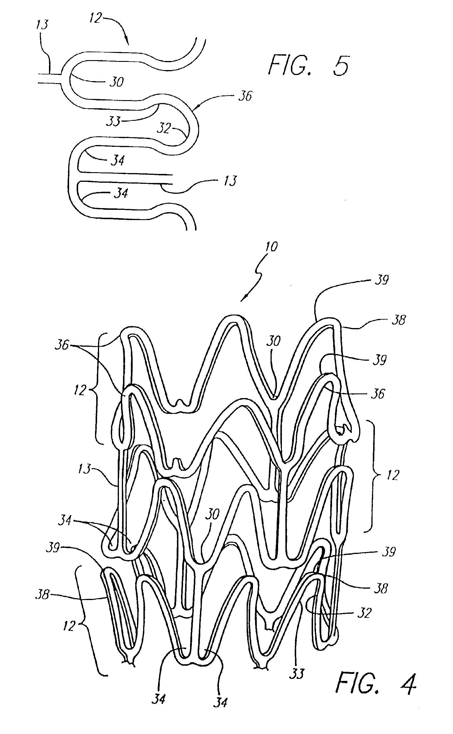
The present invention is directed to stents of enhanced longitudinal flexibility and configuration which permit the stents to expand radially to accommodate a greater number of different diameter vessels, both large and small, than heretofore was possible. The stents of the instant application also have greater flexibility along their longitudinal axis to facilitate delivery through tortuous body lumens, but remain highly stable when expanded radially, to maintain the patency of a body lumen such as an artery or other vessel when implanted therein. The unique patterns of the stents of the instant invention permit both greater longitudinal flexibility and enhanced radial expansibility and stability compared to prior art stents.
Increasing or decreasing strut length in each section changes the moment arm and consequently the radial strength of that section. Increasing or decreasing strut width at a constant strut thickness changes the cross-sectional area of the strut and the bending moment. Hence, a wider strut has greater hoop strength and is more resistant to bending.

Problems solved by technology

One of the difficulties encountered using prior art stents involved maintaining the radial rigidity needed to hold open a body lumen while at the same time maintaining the longitudinal flexibility of the stent to facilitate its delivery and accommodate the often tortuous path of the body lumen.
Another problem area has been the limited range of expandability.
Certain prior art stents expand only to a limited degree due to the uneven stresses created upon the stents during radial expansion.
This necessitates providing stents with a variety of diameters, thus increasing the cost of manufacture.
Another problem with the prior art stents has been contraction of the stent along its longitudinal axis upon radial expansion of the stent.
This can cause placement problems within the artery during expansion.

Method used


Image

  • Variable strength stent
  • Variable strength stent
  • Variable strength stent

Examples


Embodiment Construction

Prior art stent designs, such as the MultiLink Stent™ manufactured by Advanced Cardiovascular Systems, Inc., Santa Clara, Calif., include a plurality of cylindrical rings that are connected by three connecting members between adjacent cylindrical rings. Each of the cylindrical rings is formed of a repeating pattern of U-, Y-, and W-shaped members, typically having three repeating patterns forming each cylindrical ring. A more detailed discussion of the configuration of the MultiLink Stent™ can be found in U.S. Pat. No. 5,569,295 (Lam) and U.S. Pat. No. 5,514,154 (Lau et al.), whose contents are hereby incorporated by reference.

Beyond those prior art stents, FIG. 1 illustrates an exemplary embodiment of stent 10 incorporating features of the present invention, which stent is mounted onto delivery catheter 11. Stent 10 generally comprises a plurality of radially expandable cylindrical elements 12 disposed generally coaxially and interconnected by interconnecting members 13 disposed be...


PUM


Abstract

An expandable stent for implantation in a body lumen, such as an artery, is disclosed. The stent consists of a plurality of radially expandable cylindrical elements generally aligned on a common longitudinal stent axis and interconnected by one or more interconnecting members placed so that the stent is flexible in the longitudinal direction. The strength of the stent at a center section or at either end can be varied by increasing the mass of the struts forming each cylindrical element in that center section or end section relative to the lower mass struts in the remaining sections of the stent. Increasing the mass of the struts can be accomplished by, for a given strut thickness, increasing the width of the strut, or increasing the length of a cylindrical element.

Description

BACKGROUND OF THE INVENTIONThe present invention relates to expandable endoprosthesis devices, generally known as stents, which are designed for implantation in a patient's body lumen, such as blood vessels to maintain the patency thereof. These devices are particularly useful in the treatment and repair of blood vessels after a stenosis has been compressed by percutaneous transluminal coronary angioplasty (PTCA), percutaneous transluminal angioplasty (PTA), or removed by atherectomy or other means.Stents are generally cylindrically-shaped devices which function to hold open and sometimes expand a segment of a blood vessel or other lumen such as a coronary artery. They are particularly suitable for use to support the lumen or hold back a dissected arterial lining which can occlude the fluid passageway therethrough.A variety of devices are known in the art for use as stents and have included coiled wires in a variety of patterns that are expanded after being placed intraluminally on ...

Claims


Application Information

Patent Timeline
Patent Type & Authority Patents(United States)
IPC IPC(8): A61F2/06A61F2/00A61F2/84A61F2/90
CPCA61F2/91A61F2/915A61F2002/91508A61F2002/91516A61F2230/0054A61F2002/91533A61F2002/91575A61F2250/0036A61F2002/91525
Inventor COX, DANIEL L.LIMON, TIMOTHY A.
Owner ABBOTT CARDIOVASCULAR
Learn More