
Spin-hemodialysis assembly and method

a technology of hemodialysis and assembly, which is applied in the direction of centrifuges, separation processes, filtration separation, etc., can solve the problems of many responses, poor substitute for kidney function of man-made membranes, and high cost of patient care, so as to reduce the time required for blood purification and reduce the effect of life-threatening consequences

Inactive Publication Date: 2005-02-08
DENCO
View PDF30 Cites 28 Cited by
  • Summary
  • Abstract
  • Description
  • Claims
  • Application Information

AI Technical Summary

Benefits of technology

It is an object of the invention to reduce or eliminate the life-threatening consequences of the basic life saving process of dialysis, while at the same time reduce the time required to cleanse the patient's blood.
It is a further object of the invention to provide an assembly and method to separate cells and plasma in such a way as to not have the cells in contact with the artificial membrane, thereby reduce the plethora of clinical problems associated with the membrane, resulting in safer and more efficient dialyzing therapy.

Problems solved by technology

Hemodialysis essentially mimics the kidney function of processing whole blood, however, man-made membranes are a poor substitute for one's kidney function.
The cells are also very fragile, so although they do not participate in the dialysis process directly, they do come in contact with the dialyzing membrane.
The responses are numerous and in some instances life threatening.

Method used


Image

  • Spin-hemodialysis assembly and method
  • Spin-hemodialysis assembly and method
  • Spin-hemodialysis assembly and method

Examples


Embodiment Construction

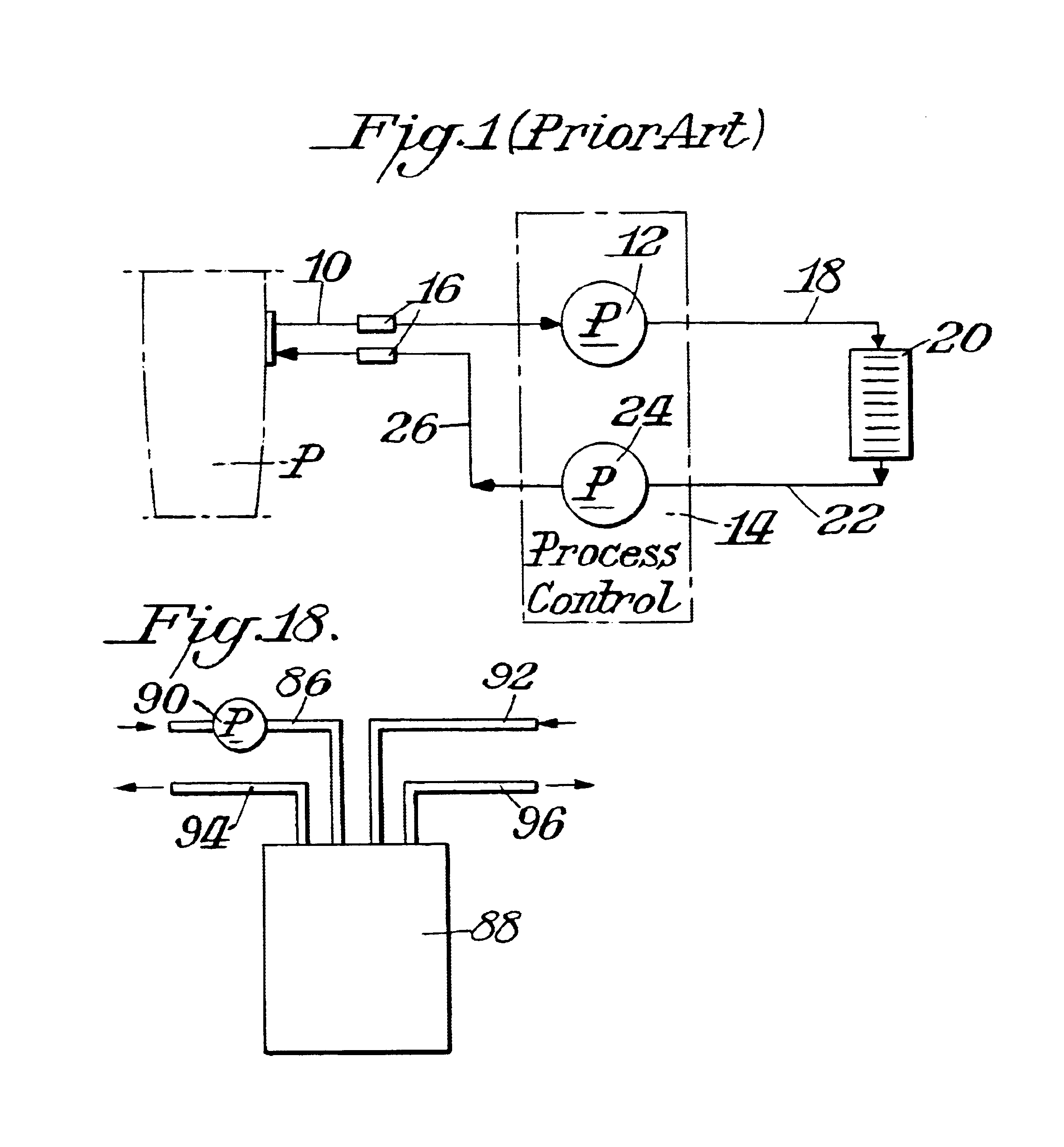
FIG. 1 represents a current prior art hemodialysis assembly. As shown therein a tube 10 is connected to the chest or arm of a patient P. A pump 12 in a process control 14 withdraws whole blood from the patient P into tube 10. The whole blood passes through a bacteria filter 16, to process control 14 and then is removed from the process control 14 through tube 18 which leads to a dialyzer 20. Dialyzer 20 may be, for example, a component commercially available from such companies as Baxter, Gambro and Fresenius. The whole blood is treated to remove contaminants in dialyzer filter 20 and the blood is then conveyed through tube 22 by means of pump 24 in process control 14. The blood is then returned to the patient P through tube 26 which incorporates a further bacteria filter 16.

The dialyzer 20 removes urea molecules from the plasma via Donan dialysis. Because, however, the red cells and the white cells or leukocytes are present, this process is hazardous in particular for the red cells...


PUM

PropertyMeasurementUnit
time periodaaaaaaaaaa
distanceaaaaaaaaaa
distanceaaaaaaaaaa

Abstract

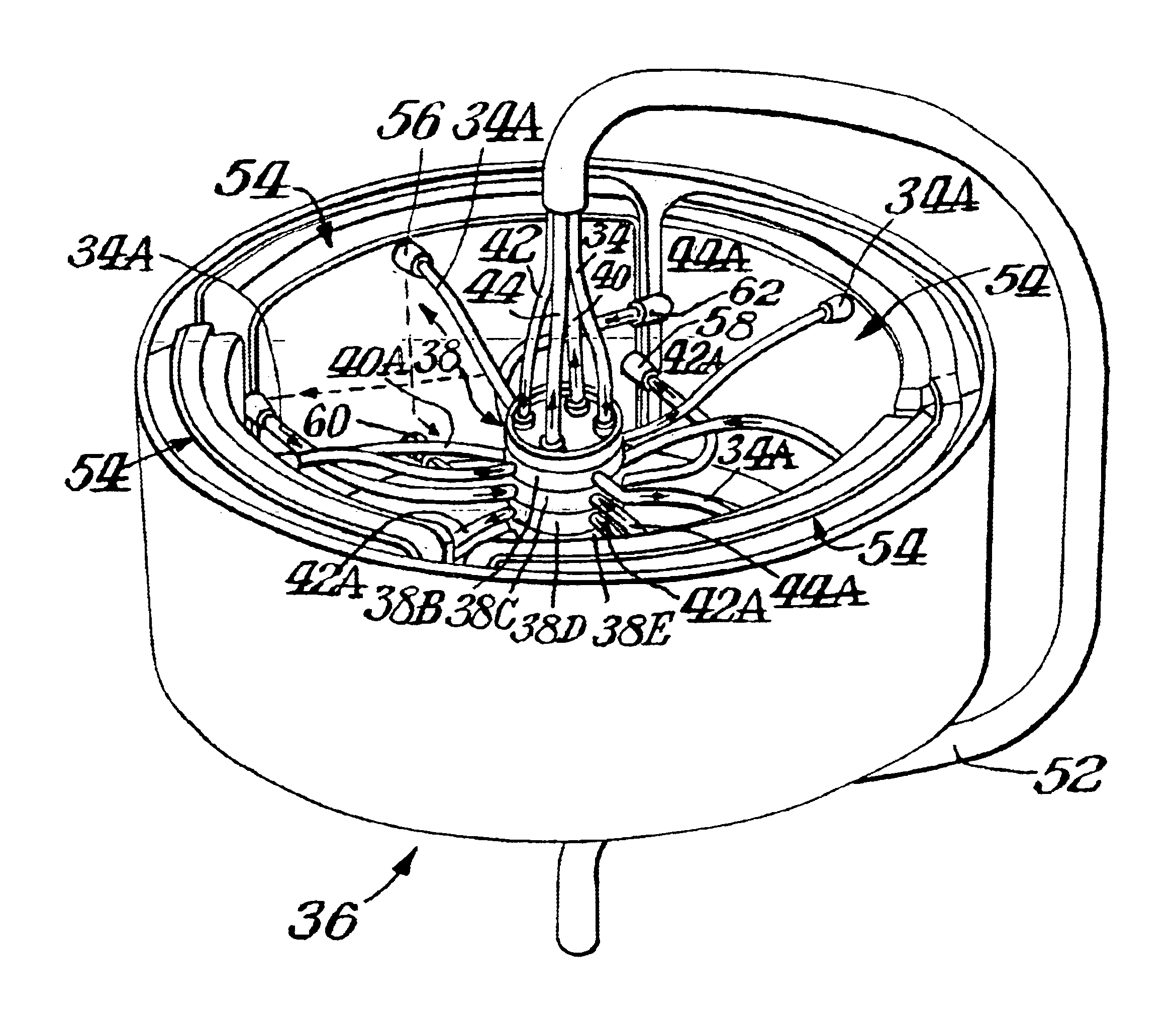
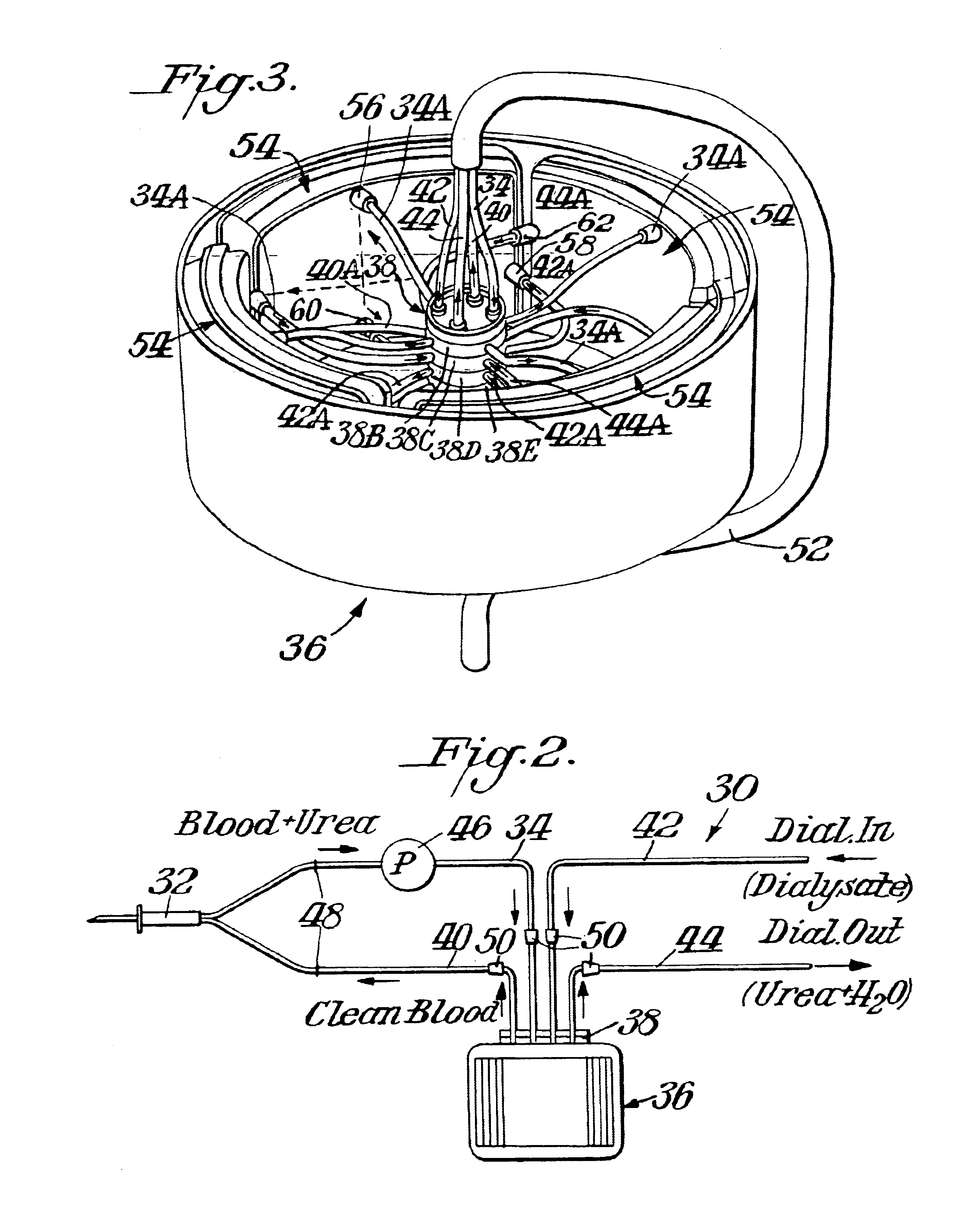
Blood is purified by removing the whole blood from a patient and feeding the blood into a manifold in a centrifuge. A purifying chamber is formed in the centrifuge from a plurality of co-arcuately arranged modules. The blood is supplied from the manifold to each of the modules. Each module contains a stack of dialysate membranes. Fresh dialysate is fed into the manifold and then to each of the modules. Under centrifugal force the cells are separated from the plasma. The plasma is purified by removing contaminants as a result of the action of the dialysate and membranes. The purified blood is returned to the patient by being fed back to the manifold and then to the patient. The used dialysate / contaminants are fed from the modules back to the manifold and out of the centrifuge.

Description

BACKGROUND OF THE INVENTIONHemodialysis was advanced as a life sustaining therapy for end-stage renal failure, when in about 1925 it was discovered that a thin film of re-constituted cellulose (cellophane®) had the ability to separate chemical substances while in solution by means of their unequal diffusion through a permeable membrane. This phenomenon performed particularly well with blood to differentially separate out urea molecules. Over the years there have been many changes to incrementally improve the hemodialysis process. The fundamentals, however, remained the same. Hemodialysis essentially mimics the kidney function of processing whole blood, however, man-made membranes are a poor substitute for one's kidney function.Whole blood is made up of four major components: a) red blood cells, b) white blood cells, c) platelets, and d) plasma fluid. Since the toxins or ureas to be removed are in the plasma solution liquid portion of the whole blood, the cells just go along for the ...

Claims


Application Information

Patent Timeline
Patent Type & Authority Patents(United States)
IPC IPC(8): A61M1/36A61M1/16B01D61/24B01D61/28B01D61/30B01D63/08B01D63/16B01D61/18B01D61/14B01D21/26B04B5/00B04B5/04A61M1/26
CPCA61M1/16A61M1/3696B01D61/14B01D61/18B01D61/243B01D61/28B01D61/30B01D63/081B01D63/084B01D63/085B01D63/16B04B5/0442B01D21/262A61M1/262A61M1/3693B01D2221/10
Inventor IVANSONS, IVARS V.SPENCER, DUDLEY W. C.
Owner DENCO
Learn More