
Flat light source

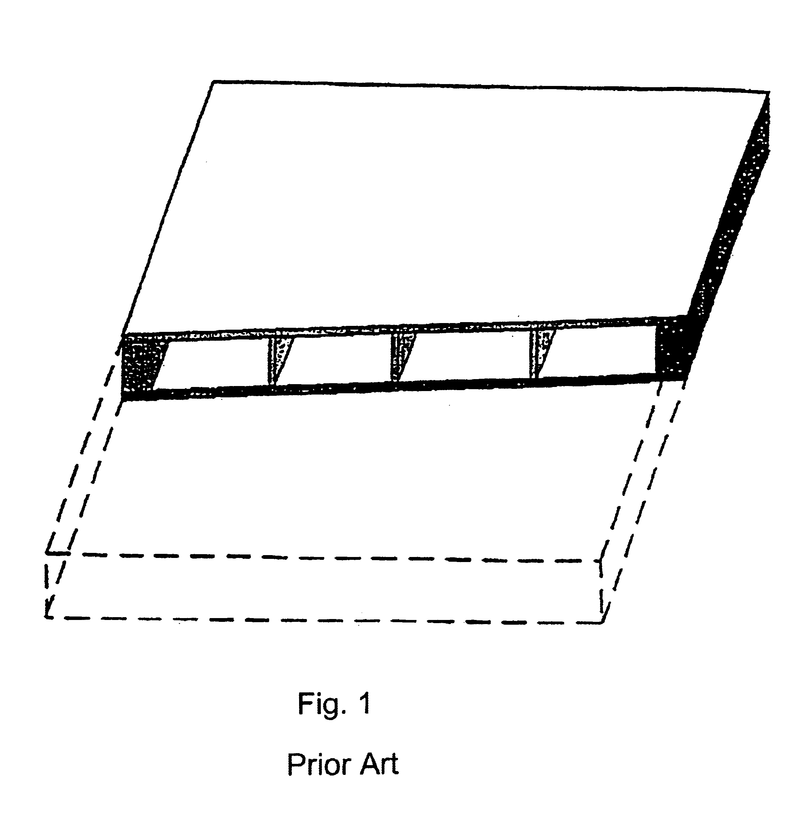
a radiator and large area technology, applied in the direction of discharge tube luminescnet screens, glass shaping apparatus, cathode-ray/electron beam tube vessels/containers, etc., can solve the problems of large thickness and large weight of the underpressure filling area radiator, and too large mechanical stress in the pane between the spacer elements, so as to achieve the effect of increasing the stability under load of the spacer elements and increasing the strength of the larg

Inactive Publication Date: 2005-02-08
SCHOTT AG
View PDF13 Cites 22 Cited by
  • Summary
  • Abstract
  • Description
  • Claims
  • Application Information

AI Technical Summary

Benefits of technology

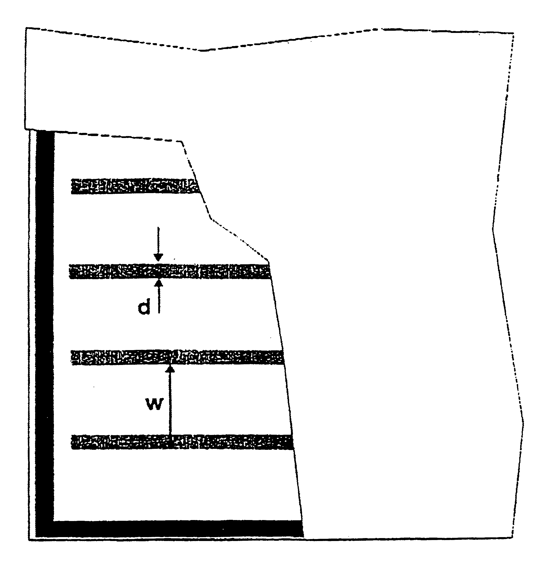
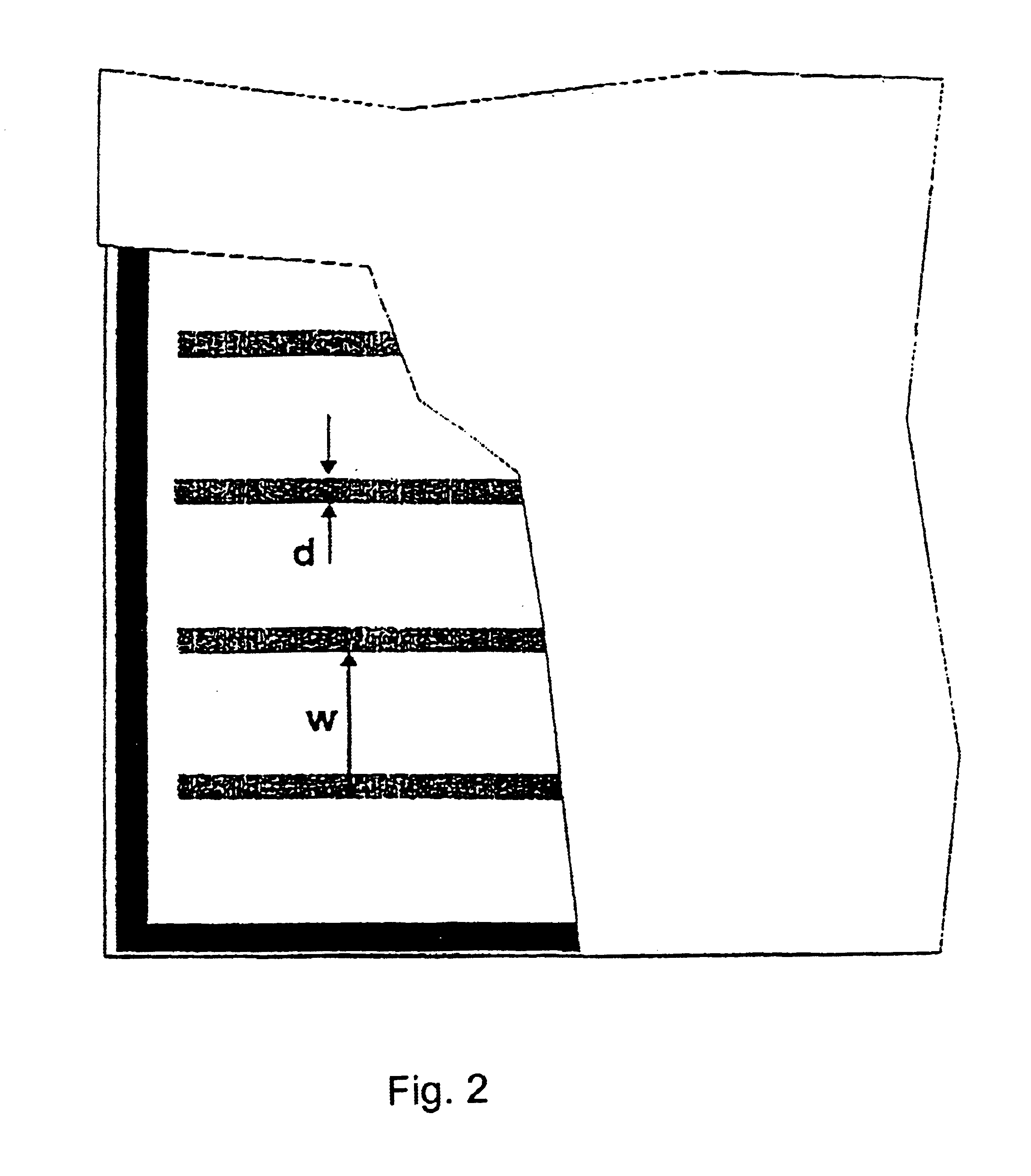
It was found that the strength of the large-area radiators can be considerably increased if the stability under load of the spacer elements is increased by using wavy spacer elements instead of straight spacer elements.

Problems solved by technology

A considerable disadvantage of large-area radiators with an underpressure filling is the great thickness and large weight.
It is known that when employing thinner glass panes for the front and rear pane, for example for weight-saving or for reducing the thickness of the large-area radiator, the following problems occur: too large mechanical stresses in the panes; too great bending of the panes between spacer elements; and buckling, tipping over or tearing off of the spacer elements.
The mechanical stresses in the panes because of the exterior pressure are considered to be a main problem.
This results in an increased production outlay and a reduction of the light yield because of the many spacer elements.

Method used


Image

  • Flat light source
  • Flat light source
  • Flat light source

Examples


embodiment 1

The rear pane of a large-area radiator, which itself is finished and capable of functioning, is sprayed with a thin coat of a two-component silicon polymer after the last baking process, so that a continuous wetting layer is created. The layer is then polymerized. The amount of silicon polymer is set so that a polymer coating of 40 to 45 μm thickness results.

embodiment 2

A large-area radiator of 320×360 mm size is to be provided with a a chemically tempered front pane of 1.1 mm thickness. Glass D263, for example DESAG AG of Grünenplan, is used for the front pane. 1.1 mm thick panes made of this glass are dipped for 16 h in a hot KNO3 bath at 450° C. in order to temper them by the “Na —K exchange”. By means of this, tempering of more than 230 MPa is created in a surface layer to a depth of 80 μm. It was observed that, in the subsequent processes in the course of producing the large-area radiator, a portion of the tempering was “washed out” again, but tempering of more than 200 MPa was observed to be a permanent value.

Flat Light Source

The invention relates to a large-area radiator with a front pane and a rear element, wherein the front pane is kept apart from the rear element by means of spacer elements, wherein a gaseous filler has been introduced into the space between the front pane and the rear element and is at a lesser pressure than the pressure...

exemplary embodiment 1

The rear pane of a large-area radiator, which itself is already finished and capable of functioning, is sprayed with a thin coat of a two-component silicon polymer after the last baking process, so that a continuous wetting layer is created. The layer is then polymerized. The amount of silicon polymer is set in such a way that a polymer coating of 40 to 45 μm thickness results.


PUM

PropertyMeasurementUnit
Lengthaaaaaaaaaa
Lengthaaaaaaaaaa
Thicknessaaaaaaaaaa

Abstract

A flat light source having a front plate and a rear part. The front plate is held at a distance from the rear part by spacers. A gaseous filling which is under a pressure lower than the ambient atmospheric pressure is introduced into the intermediate space between the front plate and rear part, and the front plate is of a glass material. To be able to produce flat light sources of this type which have a low intrinsic weight, according to this invention the front plate and / or the rear part can be configured as an at least partly thermally or chemically tempered glass pane or the front plate and / or the rear part can be configured as a glass pane which at least in areas is coated with ductile polymer material.

Description

BACKGROUND OF THE INVENTION1. Field of the InventionThis invention relates to a large-area radiator with a front pane and a rear element, wherein the front pane is kept apart from the rear element by spacer elements, a gaseous filler is introduced into the space between the front pane and the rear element and is at a lesser pressure than the pressure of the surrounding atmosphere, and the front pane is made of a glass material.2. Description of Related ArtTransmissive LCDs require background illumination by a strong light of homogeneous luminance, reduced thickness, low rate of breakage during assembly and handling, and with a great strength over time. Gas discharge lamps with a filling of a noble gas at underpressure meet the requirements of homogeneous luminance and low heat emission. These lamps can also be designed as large-area radiators.The main mechanical components of such large-area radiators are the front and rear pane and spacer elements for keeping the front and rear pan...

Claims


Application Information

Patent Timeline
IPC IPC(8): B32B17/10B32B17/06C03B17/02C03B17/00C03C17/32C03C17/28C03C17/00C03C17/30G02F1/13G02F1/1333H01J61/30H01J5/08H01J11/00H01J17/00H01J19/57H01J29/86H01J29/88H01J61/35
CPCB32B17/10018B32B17/10577C03B17/02C03C17/30C03C17/32C03C17/007G02F1/133305Y02P40/57G02F1/1335
Inventor NATTERMANN, KURTSEIBERT, VOLKERBURKLE, ROLANDKASSNER, REINHARD
Owner SCHOTT AG
Learn More