Supercharge Your Innovation With Domain-Expert AI Agents!

Recording apparatus, motor control apparatus, and motor control method

a technology of motor control and recording apparatus, applied in the direction of electric controller, program control, electric programme control, etc., can solve the problems of servo operation unstable, servo operation unstable, and the accuracy of detecting speed information decreasing

Inactive Publication Date: 2005-02-08
CANON KK
View PDF16 Cites 5 Cited by
  • Summary
  • Abstract
  • Description
  • Claims
  • Application Information

AI Technical Summary

Benefits of technology

It also has an object to provide a motor control apparatus and the like which stabilize motor control by updating control information at shorter intervals than the conventional, single-phase, single-edge sampling method.

Problems solved by technology

Thus, in servo control of a motor, any time lag between a current feature value of the controlled object and speed information fed back can make the servo operation unstable.
If the double-edge sampling method is used to solve the above problem, although speed information is updated at shorter intervals, the accuracy of detecting speed information decreases due to variations in the duty cycle for the reasons described above, making the servo operation unstable.

Method used


Image

  • Recording apparatus, motor control apparatus, and motor control method
  • Recording apparatus, motor control apparatus, and motor control method
  • Recording apparatus, motor control apparatus, and motor control method

Examples


first embodiment

[First Embodiment]

With reference to drawings, detailed description will be given of how the motors are controlled in the above described recording apparatus. FIGS. 4A to 4D are diagrams illustrating a calibration process.

FIG. 4A shows a waveform of an interrupt signal for motor control which is based on detection information. This interrupt signal is output periodically from a servo controller described later.

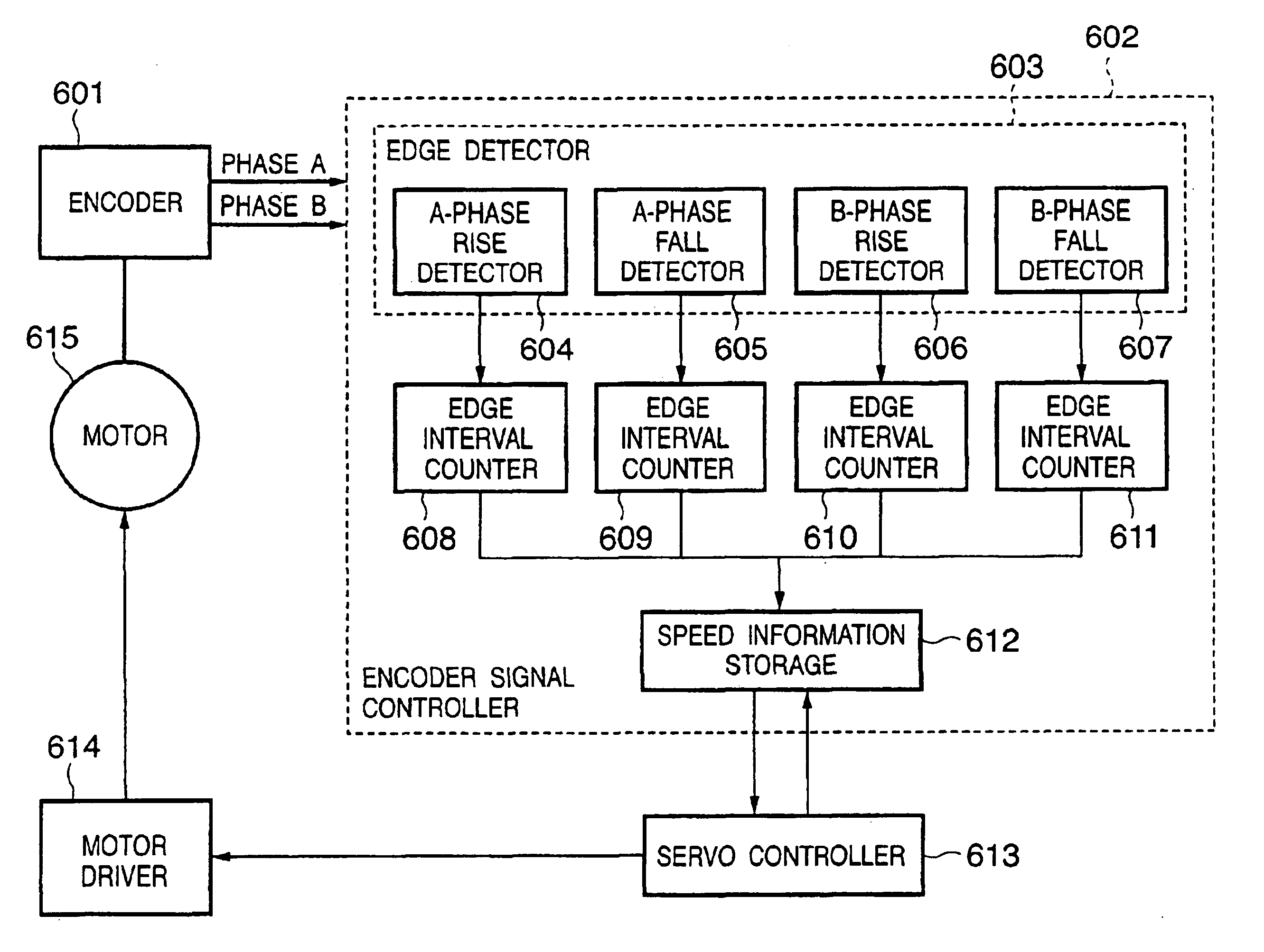
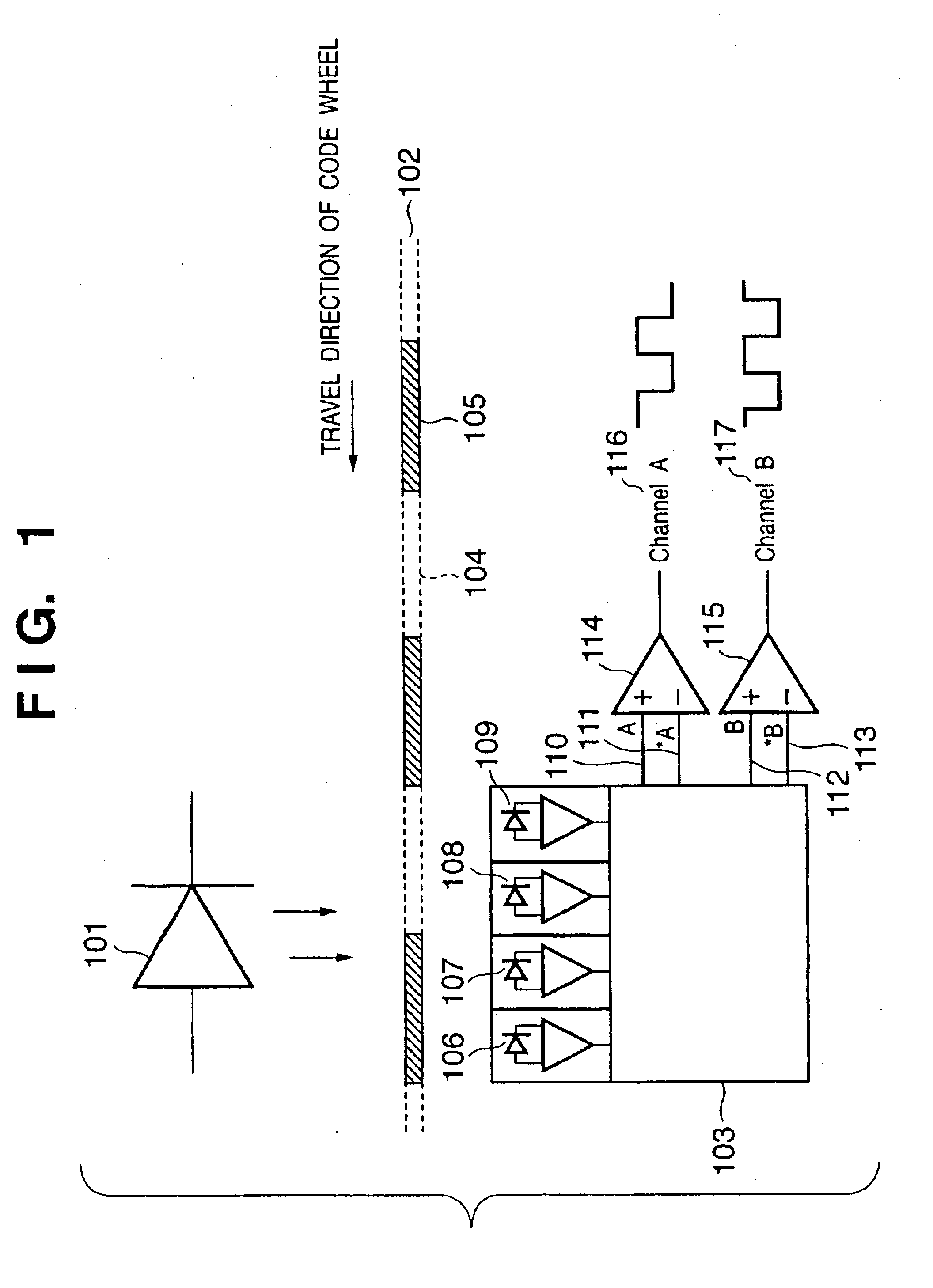
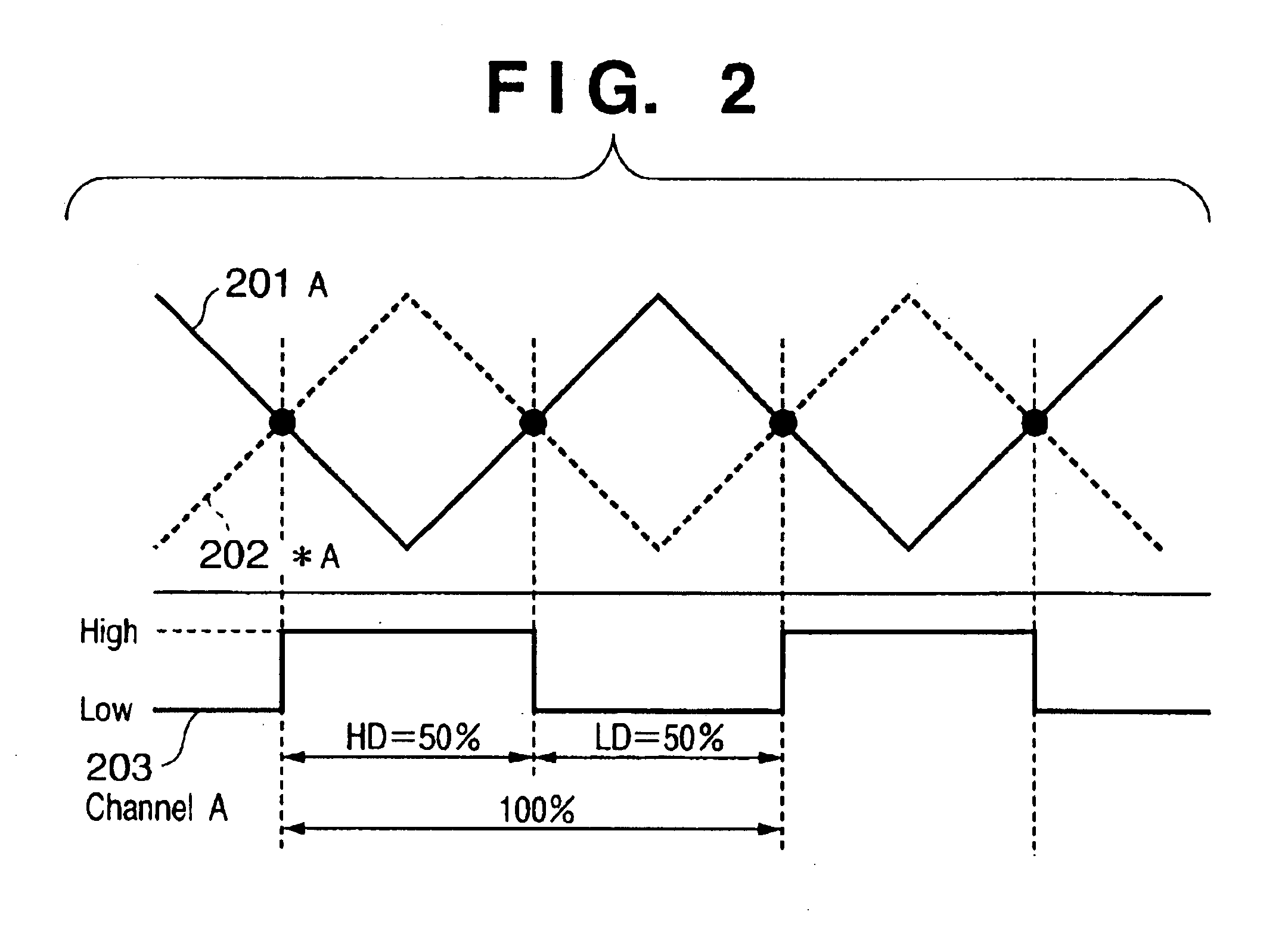
FIGS. 4B and 4C show output waveforms of different phases A and B produced by an encoder (e.g., rotary encoder), and FIG. 4D shows an edge-to-edge sampling waveform of speed information. The interrupt signal in FIG. 4A looks as if it were synchronized with the signals outputted from the encoder in FIGS. 4B and 4C, but actually it has predetermined cycles (servo cycles) and are not synchronized with the encoder signals.

Constant-speed driving is performed by single-phase, single-edge (int1 in FIGS. 4A to 4D) speed information which high accuracy is ensured, and speed information ...


PUM


Abstract

A motor control apparatus which can improve detection accuracy of control information and stabilize a control system includes a detector for detecting first pulse information which corresponds to the drive speed of a driven object and second pulse information out of phase with the first pulse information; edge detectors for detecting rising edges and falling edges of the detected first pulse information and second pulse information; edge interval measuring units for measuring edge-to-edge periods using the detected rising edges and falling edges; a calibrator for calibrating the measured edge-to-edge periods with a reference period for driving the driven object at constant speed; a corrector for correcting the first pulse information and second pulse information based on the calibration; and a controller for generating control commands to drive the driven object based on the corrected first pulse information and second pulse information.

Description

FIELD OF THE INVENTIONThe present invention relates to a recording apparatus, motor control apparatus, and motor control method which are distinguished by controlling of a DC motor used as a driving source of the recording apparatus.BACKGROUND OF THE INVENTIONInk jet recording apparatuses are widely used, being mounted on a printer, facsimile machine, or copying apparatus, as a means of recording images (including characters and symbols) on a recording medium such as paper or plastic sheets (OHP or the like) based on image information. The ink jet recording apparatuses perform recording by discharging ink droplets onto a recording medium from a recording head. They have the advantage that they can downsize a mechanism for performing recording processes and can record accurate images at high speed. Moreover, they feature low running costs and have a low noise level because of their non-impact design. In addition, they can easily record color images using inks other than black: cyan (...

Claims


Application Information

Patent Timeline
IPC IPC(8): G05B19/19G05B19/29G05B11/01B41J13/00
CPCB41J13/0009
Inventor KOBAYASHI, NOBUTSUNESHOJI, MICHIHARU
Owner CANON KK
Features
  • R&D
  • Intellectual Property
  • Life Sciences
  • Materials
  • Tech Scout
  • Unparalleled Data Quality
  • Higher Quality Content
  • 60% Fewer Hallucinations
Learn More