Video camera-based visibility measurement system

a video camera and visibility measurement technology, applied in the direction of measurement devices, instruments, scientific instruments, etc., can solve the problems of reducing the visibility in the atmosphere, slms will report a very large error, slms are prone to providing incorrect visibility readings, etc., to achieve accurate measurements of atmospheric visibility and reduce costs.

Inactive Publication Date: 2005-02-08
RGT UNIV OF MINNESOTA
View PDF8 Cites 16 Cited by
  • Summary
  • Abstract
  • Description
  • Claims
  • Application Information

AI Technical Summary

Benefits of technology

The present invention overcomes the disadvantages and limitations of the prior art by providing a system that can accurately measure atmospheric visibility in a manner that is similar to the manner in which the human eye perceives atmospheric visibility. The present invention can also utilize existing equipment that is used for other purposes, such as a video camera, which will additionally allow verification of automatic visibility measurements made by the system.
The advantages of the present invention are that it can provide very accurate measurements of atmospheric visibility during both the day and night in the same fashion that atmospheric visibility is perceived by the human eye. The system can utilize existing equipment that may be used for other purposes to reduce costs. Further, the present invention allows for manual verification which may be desired such as when important decisions need to be made regarding road closure or speed limit reductions.

Problems solved by technology

There are a number of problems, however, with measuring visibility using scattered light meters (SLMs).
First, light scattering by atmospheric particles such as atmospheric moisture is only one of the effects that reduces visibility in the atmosphere.
If the local region adjacent the SLM deviates from the overall visibility, such as the visibility along a road at a distance of up to 300 meters, the SLM will report a very large error.
Hence, SLMs are prone to providing incorrect readings of visibility in adverse conditions.
While SLMs provide a fairly accurate measure of light scattering, and hence visibility under conditions of fog where atmospheric moisture is the primary contributing factor for low visibility, SLMs may provide a high margin of error for visibility measurements under rain and snow conditions for the reasons as set forth above.
The ability to determine the types and sizes of particles present in the atmosphere, as well as the ability to self-calibrate an SLM according to the types and sizes of particles detected, would greatly increase the cost of the SLM and would most likely provide results that are still prone to errors.
Additionally, SLMs do not provide an easy way to verify the correctness of the visibility that is reported by the SLM.
Since SLMs are very expensive, this greatly increases the cost, and the SLMs still suffer from the inherent problems indicated above.
Moreover, SLMs require a high degree of precision in the alignment of the transmitter and receiver optics which additionally adds to the cost of the SLM systems.

Method used


Image

  • Video camera-based visibility measurement system
  • Video camera-based visibility measurement system
  • Video camera-based visibility measurement system

Examples


Embodiment Construction

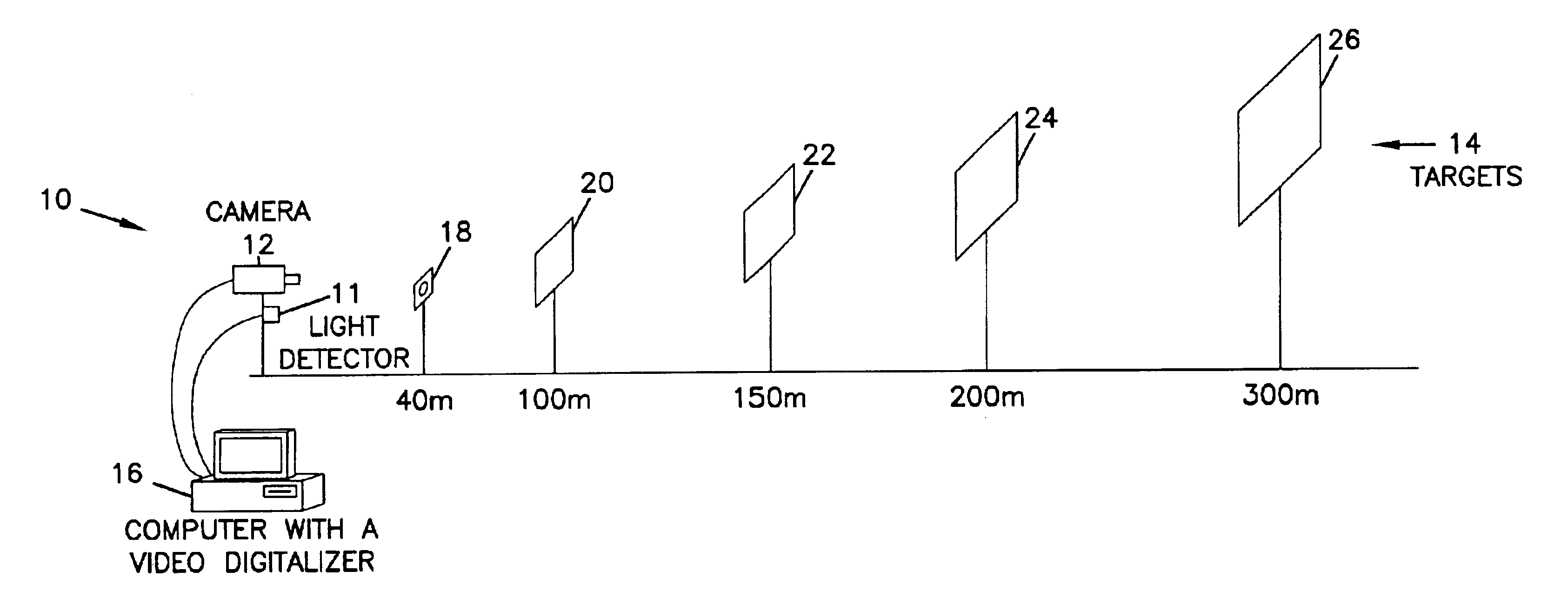
FIG. 1 is a schematic illustration of a system 10 in which the present invention can be implemented. As shown in FIG. 1, a camera such as a video camera or digital camera is aligned to view a series of targets 14 in a region in which measurement of atmospheric visibility is desired. Camera 12 can comprise any desired detector device that is capable of detecting contrasting portions of the targets 14 during daylight hours and a light source that is provided in target 18 during low light level conditions. For example, any suitable CCD array that is focused to provide an image of the targets 14 can be utilized, including video cameras, digital cameras, scanners, or other similar devices. Camera 12 should have a built-in auto iris and back light compensation function in order to obtain a good quality picture. Camera 12 may also be housed in a defrost heater having a fan to prevent frost or fog on the lens. Compressed air may also be provided to blow the lens of the camera in order to qu...


PUM

PropertyMeasurementUnit
distanceaaaaaaaaaa
distanceaaaaaaaaaa
distanceaaaaaaaaaa

Abstract

A video camera based atmospheric visibility measurement system that is capable of providing automated measurements of atmospheric visibility during both the day and night. For daylight measurements, the system views an image that has contrasting portions. A representative contrast signal is generated for contrasting portions of the images. The representative contrast number is used to generate an exponential curve of contrast levels versus distance. Atmospheric visibility is determined by detecting where the exponential curve reaches a threshold of visibility.

Description

BACKGROUND OF THE INVENTIONA. Field of the InventionThe present invention pertains generally to automated methods of measuring atmospheric visibility and, more particularly, to a video camera-based system for measuring atmospheric visibility.B. Description of the BackgroundVisibility conditions are affected by the structure and elements of the atmosphere, such as fog, snow, wind, dust, and other adverse conditions. Visibility has been defined as the greatest distance at which an object of specified characteristics can be see and detected by the naked eye. See American Meteorological Society, Glossary of Meteorology, 1989, and W. E. Knowles Middleton, Vision Through Atmosphere, 1968, University of Toronto Press. Atmospheric visibility is normally expressed in distance, such as meters or yards, or at greater distances in kilometers or miles. Atmospheric visibility at night is determined by measuring the distance from a point of light of a given intensity to a point where the light sou...

Claims


Application Information

Patent Timeline
Patent Type & Authority Patents(United States)
IPC IPC(8): G01N21/53G01N21/59G01N21/47
CPCG01N21/59G01N21/538
Inventor KWON, TAEK MU
Owner RGT UNIV OF MINNESOTA
Why Eureka
Try Eureka