Method for measuring PES noise of servo patterned media

Inactive Publication Date: 2005-02-08
SEAGATE TECH LLC
View PDF12 Cites 21 Cited by
  • Summary
  • Abstract
  • Description
  • Claims
  • Application Information

AI Technical Summary

Problems solved by technology

The other is caused by random errors ...

Method used


Image

  • Method for measuring PES noise of servo patterned media
  • Method for measuring PES noise of servo patterned media
  • Method for measuring PES noise of servo patterned media

Examples


Embodiment Construction

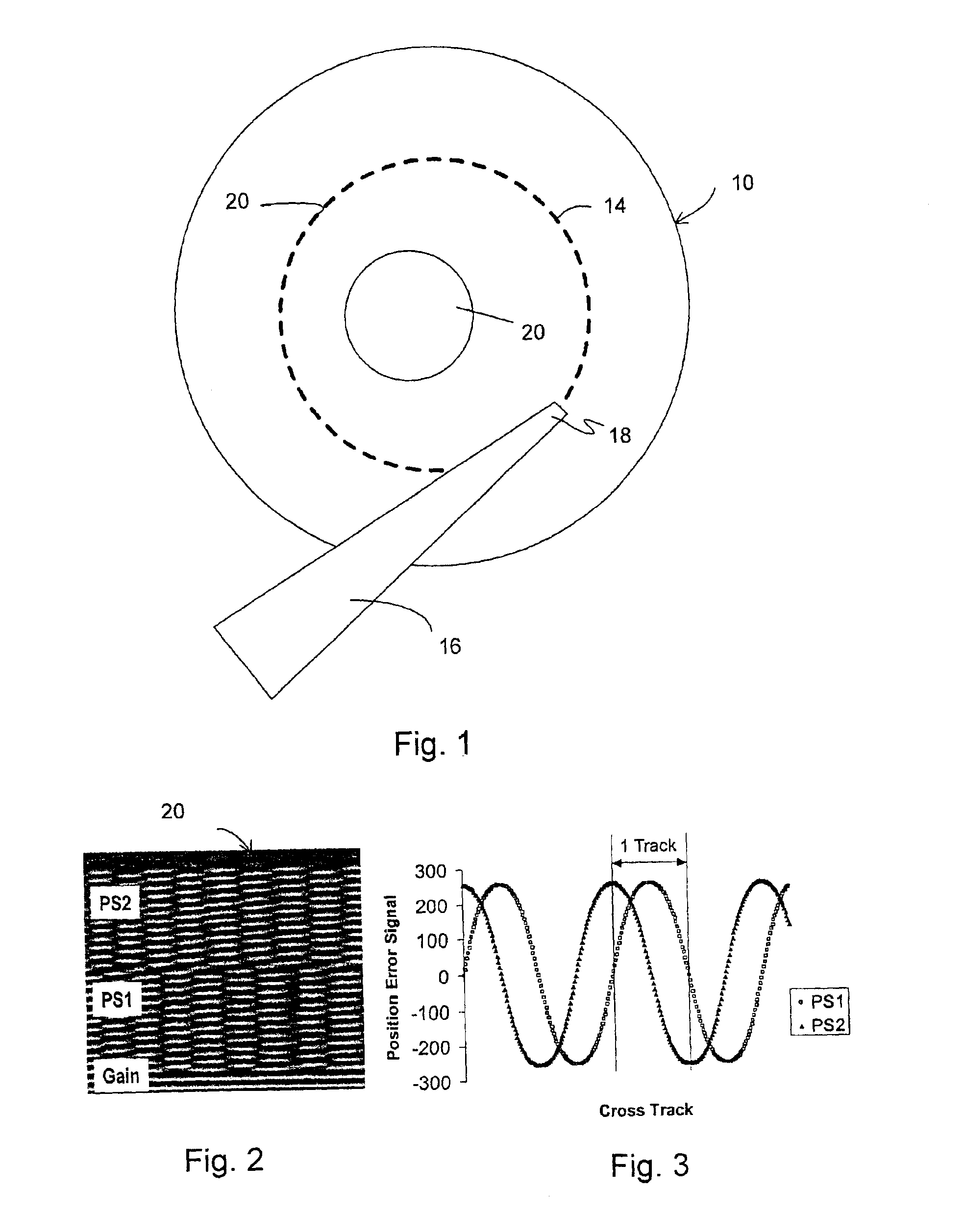
The preferred method for measuring runout is to mount the pre-patterned disc onto a spin stand spindle as illustrated in FIG. 1. A piezoelectric motor (not shown) is attached to the actuator 16. This motor steps the actuator in equal increments. Perfect step accuracy is not required, thus the expense of the stepper system can be reduced.

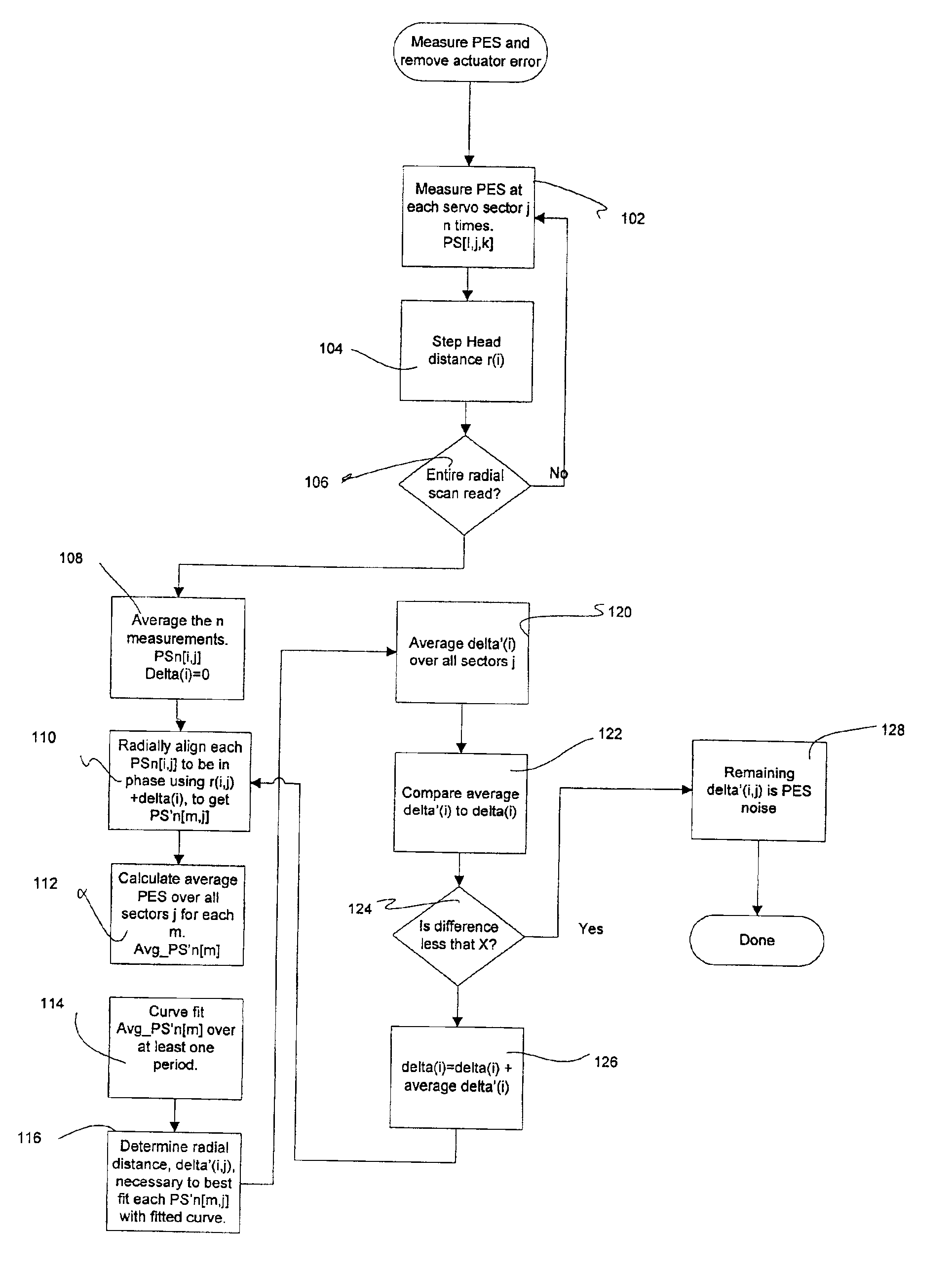
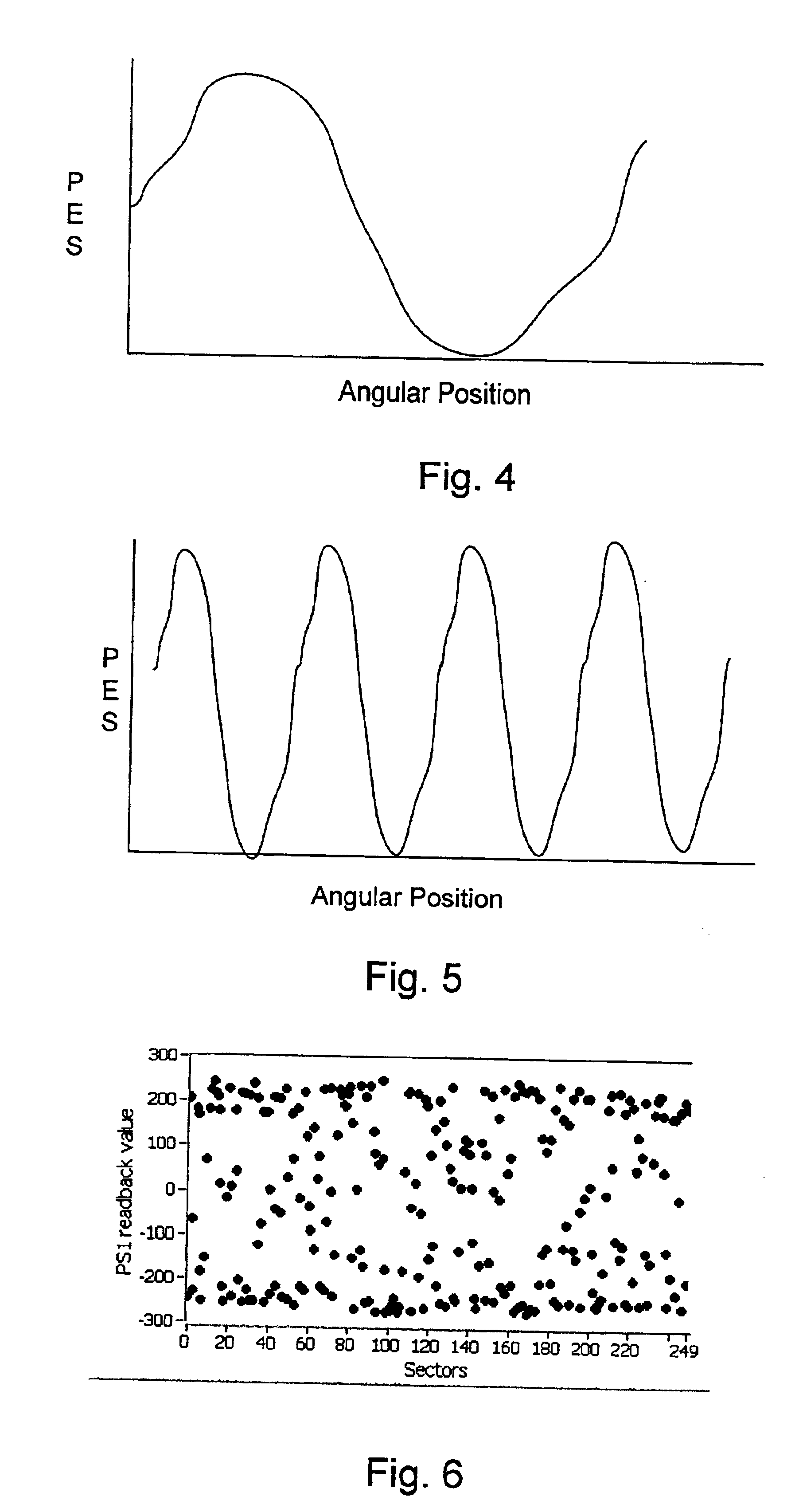
A typical disk for a disk drive will have on the order of 250 servo sectors. Each of the servo sectors typically is broken down into several sections, included among which would be Gain, PS1 and PS2 (see FIG. 2) for a so-called quadrature servo pattern. When these servo bursts are read by a magnetic head and decoded by a servo system, the servo system generates so-called PES signals that are an indication of how far the head is away from a so-called track center, which typically is thought of as the line dividing adjacent servo patterns of either PS1 or PS2 in FIG. 2. As illustrated in FIG. 3, these PES signals are periodic in the radial dimension. W...


PUM


Abstract

A method for measuring servo pattern irregularity and other servo information of pre-patterned servo media mounted on a spindle with the center of the pre-pattern tracks off center from the axis rotation of the spindle. An actuator is stepped radially while measuring the PES signals from the servo sectors of at least one highly eccentric track to form a cross track profile of the PES signals for each sector. A mathematical algorithm removes step measurement error from the data. A second mathematical algorithm removes non-repeatable random noise from the data. The amount of phase-in that radially aligns the respective cross track profiles is computed. Servo pattern written-in repeatable runout is determined by unwrapping the phase-in values to form a periodic curve.

Description

BACKGROUND OF THE INVENTION1. Field of the InventionThe invention relates to field of disk drives and more particularly to the writing of servo tracks onto the disks during manufacture.2. Description of the Related ArtDisk drive servo tracks are today written onto a blank magnetic disk after the disk drive has been substantially assembled. While there are many known methods for writing servo tracks onto a blank magnetic disk, one of the most common methods include the use of a laser interferometer to control a picker that attaches to an actuator arm. The picker steps the arms across the disk. A head, mounted on the arm writes the servo patterns.As disk drive areal density continues to increase, pre-patterned servo fields are proposed. These fields may be formed by high precision lithographic methods. See, e.g., U.S. Pat. No. 6,331,364 B1. A mask exposes areas to be demagnetized. An ion bombardment through the mask reduces the coercivity of the disk magnetic material, making it unabl...

Claims


Application Information

Patent Timeline
IPC IPC(8): G11B5/596
CPCG11B5/59633G11B5/59611
Inventor LI, XINWEIWAGO, KOICHIKUO, DAVID SHIAO-MIN
Owner SEAGATE TECH LLC
Why Eureka
Try Eureka