
Apparatus and method for driving actuator

a technology of actuators and actuators, applied in the direction of generators/motors, heads, instruments, etc., can solve the problems of reduced cost and size, uncomplete removal of unnecessary signal components, and complex structure, and achieve the effect of simple structur

Inactive Publication Date: 2005-02-08
OLYMPUS CORP
View PDF11 Cites 5 Cited by
  • Summary
  • Abstract
  • Description
  • Claims
  • Application Information

AI Technical Summary

Benefits of technology

In view of the above-described problems, it is an object of the present invention to provide an actuator drive apparatus capable of eliminating the influence of the mutual induction effect of the drive coil and the detection coil with a simple structure.
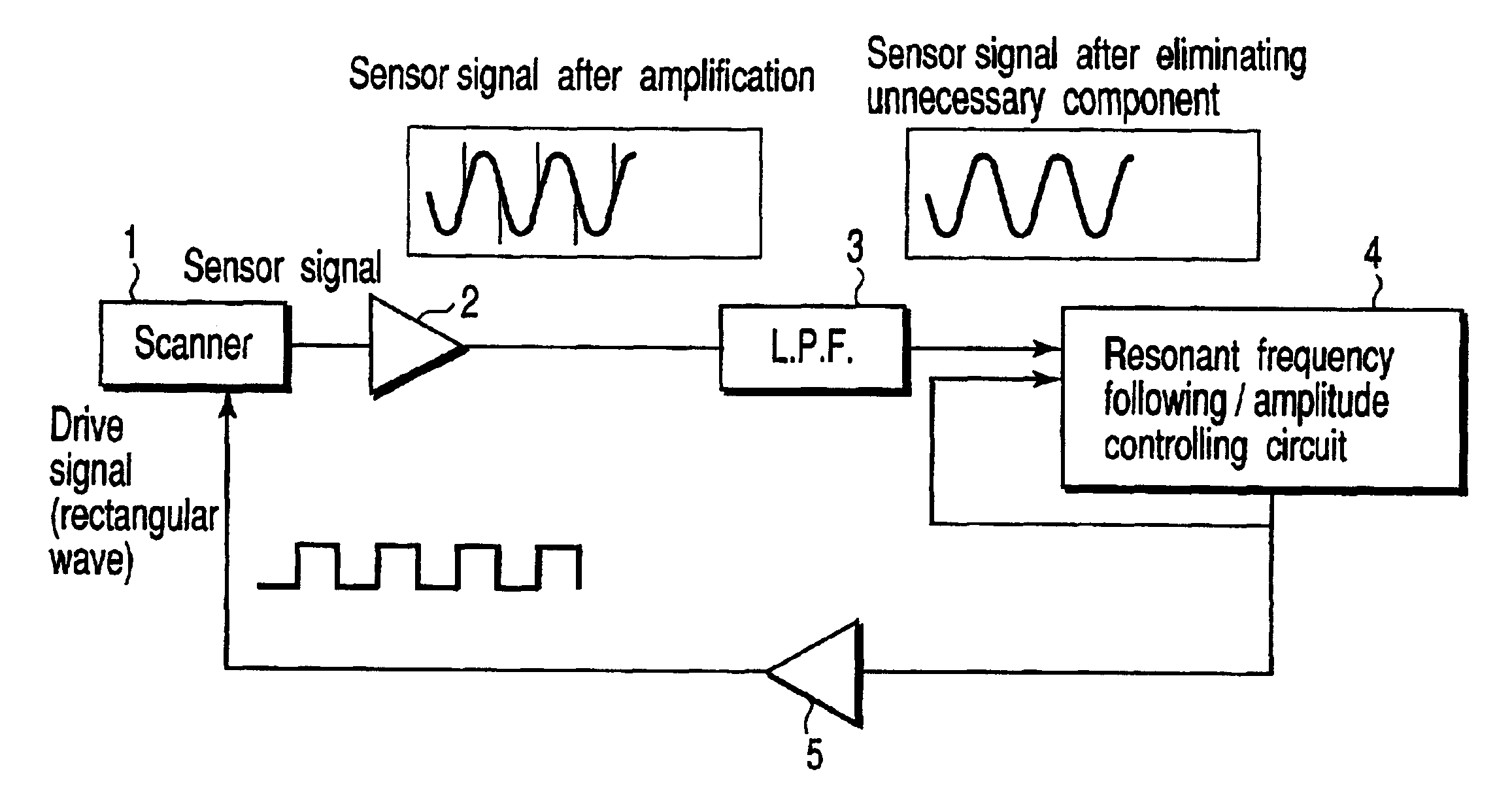
To achieve this aim, in a first mode according to the present invention, there is provided an actuator drive apparatus comprising: a movable section; a fixed section, an elastic member for connecting the movable section with the fixed section; a magnetic field generation member; a drive coil; a detection coil; a control circuit for applying a drive signal having a rectangular wave to the drive coil, the movable section thereby making a movement relative to the fixed section in the resonance state, the control circuit thereby maintaining the movement of the movable section relative to the fixed section in the resonance state; and a high frequency elimination circuit for eliminating a specific high frequency component of an output signal of the detection coil.
In a second mode, there is provided an actuator drive apparatus for driving an actuator consisting of a movable section, a fixed section, an elastic member for connecting the movable section with the fixed section, a magnetic field generation member, a drive coil, and a detection coil, the actuator drive apparatus comprising: a control circuit for applying a drive signal having a rectangular wave to the drive coil, the movable section thereby making a movement relative to the fixed section in the resonance state, and the control circuit feeding back an output signal from the detection coil to the drive signal, the movement of the movable section relative to the fixed section thereby being maintained in the resonance state; and a high frequency elimination circuit for eliminating a specific high frequency component of an output signal of the detection coil.

Problems solved by technology

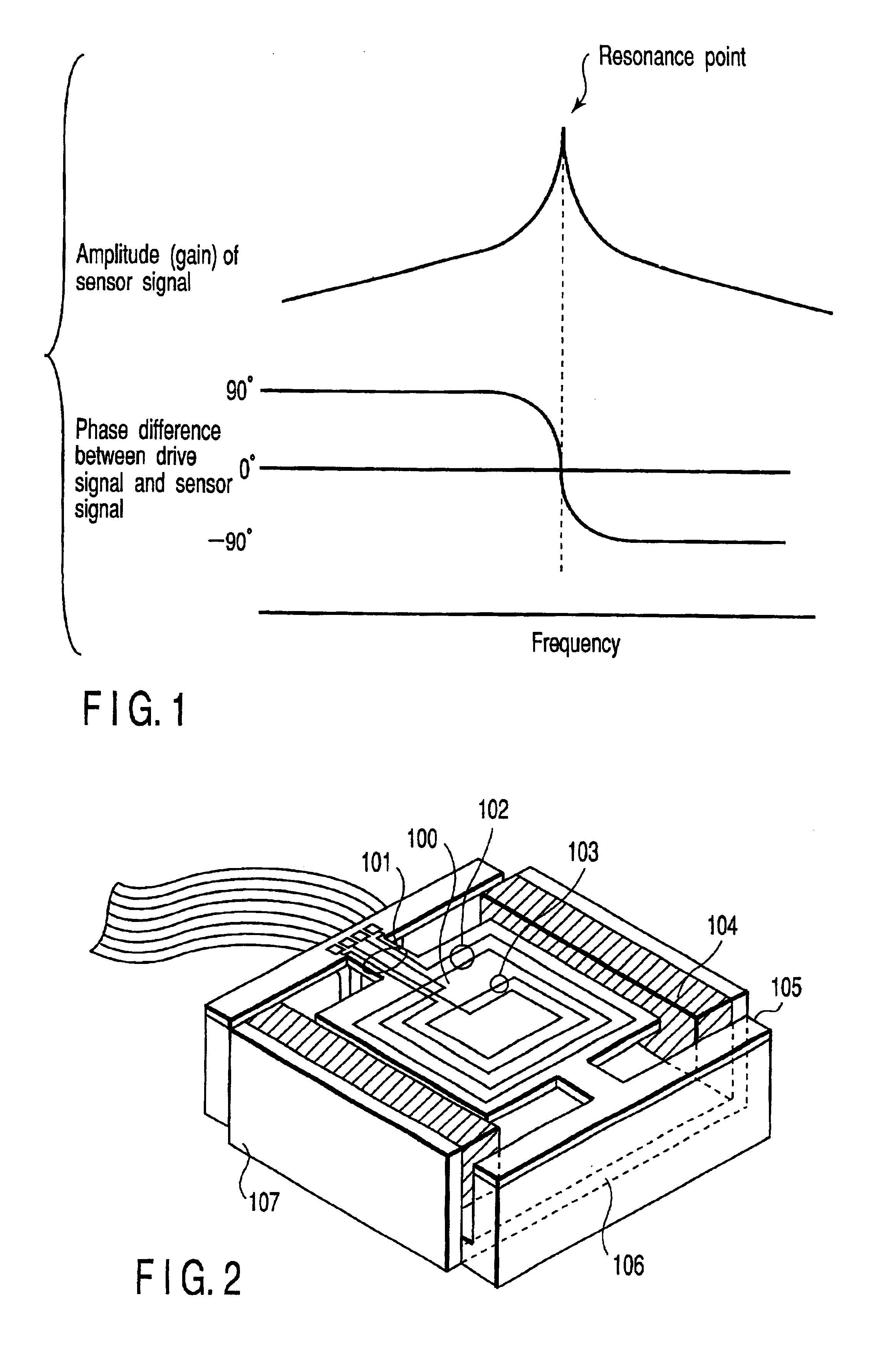
However, since the drive coil and the detection coil are actually contiguous with each other, the signal caused due to mutual induction of both the coils is disadvantageously included in the sensor signal.
However, in the technique disclosed in Japanese Patent Application KOKAI Publication No. 64-2015, since a coil must be newly provided to the fixed section, the structure becomes complicated, which may be an obstacle for reduction in cost and size.
Thus, the unnecessary signal component can not be completely removed.
In addition, in the technique disclosed in Japanese Patent Application KOKOKU Publication No. 7-70083, the magnetic shield effect of the closed magnetic circuit is utilized, but this is not perfect.
Therefore, the mutually-inductive electromotive force of the drive coil and the detection coil can not be completely removed.
Accordingly, optimization of the coil positions is difficult.

Method used


Image

  • Apparatus and method for driving actuator
  • Apparatus and method for driving actuator
  • Apparatus and method for driving actuator

Examples


second embodiment

A description will now be given as to a second embodiment solving these problems.

FIGS. 10 and 11 are block diagrams showing the structure of an actuator drive apparatus according to a second embodiment. It is to be noted that like reference numerals denote like or corresponding parts in FIG. 6 to omit explanation, and characteristic parts will be mainly described.

The structure shown in FIG. 10 is different from that in FIG. 6 in that a phase compensation circuit 6 is provided on the feedback path from the resonant frequency following / amplitude controlling circuit 4. On the other hand, the structure shown in FIG. 11 is different from that in FIG. 6 in that an output of the LPF 3 is connected to an input of the resonant frequency following / amplitude controlling circuit 4 through the phase compensation circuit 6.

Other structures are similar to that of the first embodiment.

As described above, according to the second embodiment, by using the phase compensation circuit 6 to generate the p...


PUM

PropertyMeasurementUnit
angular velocityaaaaaaaaaa
frequencyaaaaaaaaaa
magnetic fieldaaaaaaaaaa

Abstract

The present invention relates to an actuator drive apparatus capable of eliminating the influence of the mutual induction effect of a drive coil and a detection coil with a simple structure. That is, the present invention is an actuator drive apparatus capable of causing a movement of the drive coil of a scanner by applying an electric current thereto, and generating and maintaining the resonance state by feeding back an output signal of the detection coil at that moment. In particular, the present invention uses a rectangular wave as the drive signal and includes an LPF for eliminating a specific high frequency component of an output signal of the detection coil.

Description

CROSS-REFERENCE TO RELATED APPLICATIONSThis application is based upon and claims the benefit of priority from the prior Japanese Patent Application No. 2000-292937, filed Sep. 26, 2000, the entire contents of which are incorporated herein by reference.BACKGROUND OF THE INVENTIONThe present invention relates to an apparatus and a method having or using a movable section, a fixed section, an elastic member for connecting the movable section with the fixed section, magnetic field generating means, a drive coil, a detection coil and others, and more particularly to an apparatus and a method for driving an actuator by which the movable section is constantly vibrated in the resonance state.Heretofore, as an example of an electromagnetic actuator, there has been, for example, an actuator used in an optical pickup. This is used for performing tracking control with a vibrating mirror. In this actuator, both a mirror drive coil and a mirror vibration detection coil are provided on the movable...

Claims


Application Information

Patent Timeline
Patent Type & Authority Patents(United States)
IPC IPC(8): H02P25/02G11B7/135H02K33/18G11B7/09H02N2/00
CPCH02P25/027H02P25/032
Inventor MIYAJIMA, HIROSHIMIYAHARA, HIDEHARU
Owner OLYMPUS CORP
Learn More