Circuit arrangement for the electrically isolated transfer of digital signals

a technology of digital signal and circuit arrangement, which is applied in the direction of transmission line coupling arrangement, line-transmission, baseband system, etc., can solve the problems of significant technical complexity, unsuitable methods, and inability to suppress such interference, so as to achieve the effect of not reducing the edge steepness of the transmitted digital signal

Inactive Publication Date: 2005-02-08
KONRAD STEPHAN
View PDF14 Cites 11 Cited by
  • Summary
  • Abstract
  • Description
  • Claims
  • Application Information

AI Technical Summary

Benefits of technology

One advantage of the invention is that the edge steepness of the transmitted digital signals is not reduced. This means that the digital signals appearing at the output of the circuit arrangement have the same edge steepness as those applied at the input.
is that the edge steepness of the transmitted digital signals is not reduced. This means that the digital signals appearing at the output of the circuit arrangement have the same edge steepness as those applied at the input.
Another advantage of the invention is that because of the reference potential at the respective switching stage, the circuit arrangement has a defined quiescent level, to which it returns after each signal transmission.

Problems solved by technology

Due to the effect of the inductances of transformers, however, the use of the latter reduces the edge steepness of the digital signal, so that this method may be unsuitable.
In addition, transformers also transfer electromagnetic interference introduced to them, and the suppression of such interference involves a considerable amount of technical complexity.
This is not possible with the prior-art transmission channels described.
Another disadvantage associated with the use of flip-flops in such transmission channels is that their on state is not defined.

Method used


Image

  • Circuit arrangement for the electrically isolated transfer of digital signals
  • Circuit arrangement for the electrically isolated transfer of digital signals
  • Circuit arrangement for the electrically isolated transfer of digital signals

Examples


Embodiment Construction

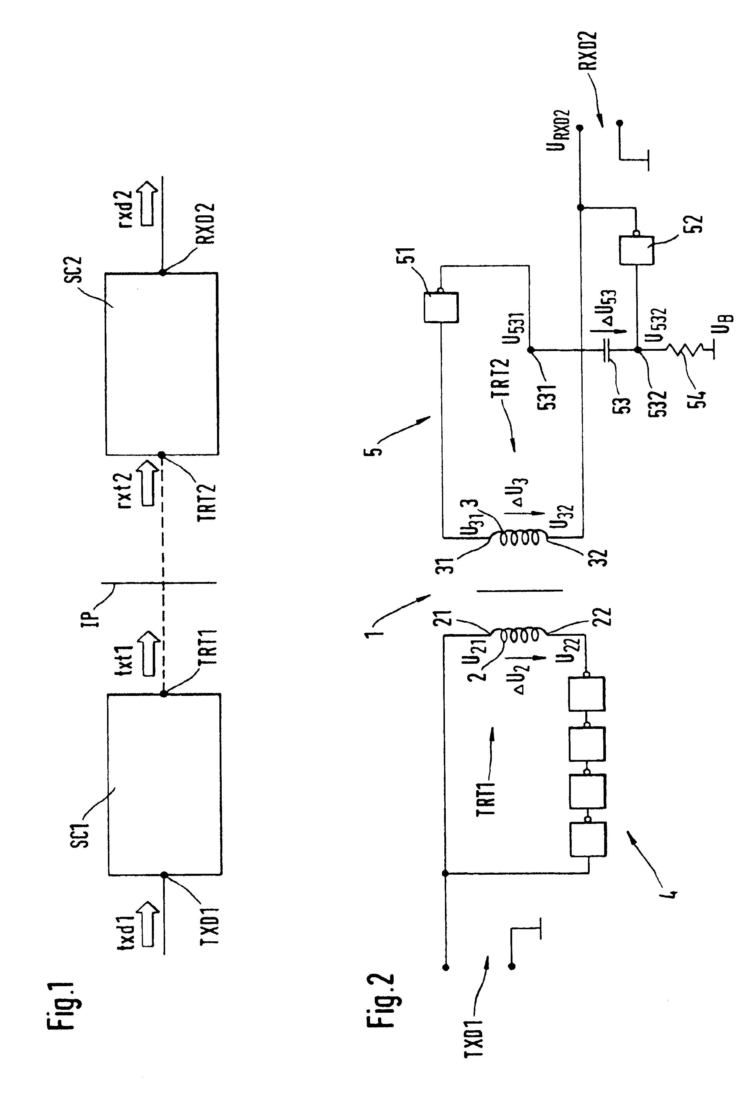
FIG. 1 shows a schematic block diagram of a transmission channel for the electrically isolated transmission of digital signals, particularly of binary signals, between a first and a second transmitter / receiver unit (not shown) in a selected direction of transmission. The digital signal can be any two-valued electric signal of predeterminable pulse width and pulse repetition rate and of predeterminable mark-to-space ratio.

The transmission channel comprises a first digital-signal port TXD1 for a first signal to be transmitted, txd1, and a second digital-signal port RXD2 for a transmitted second digital signal rxd2.

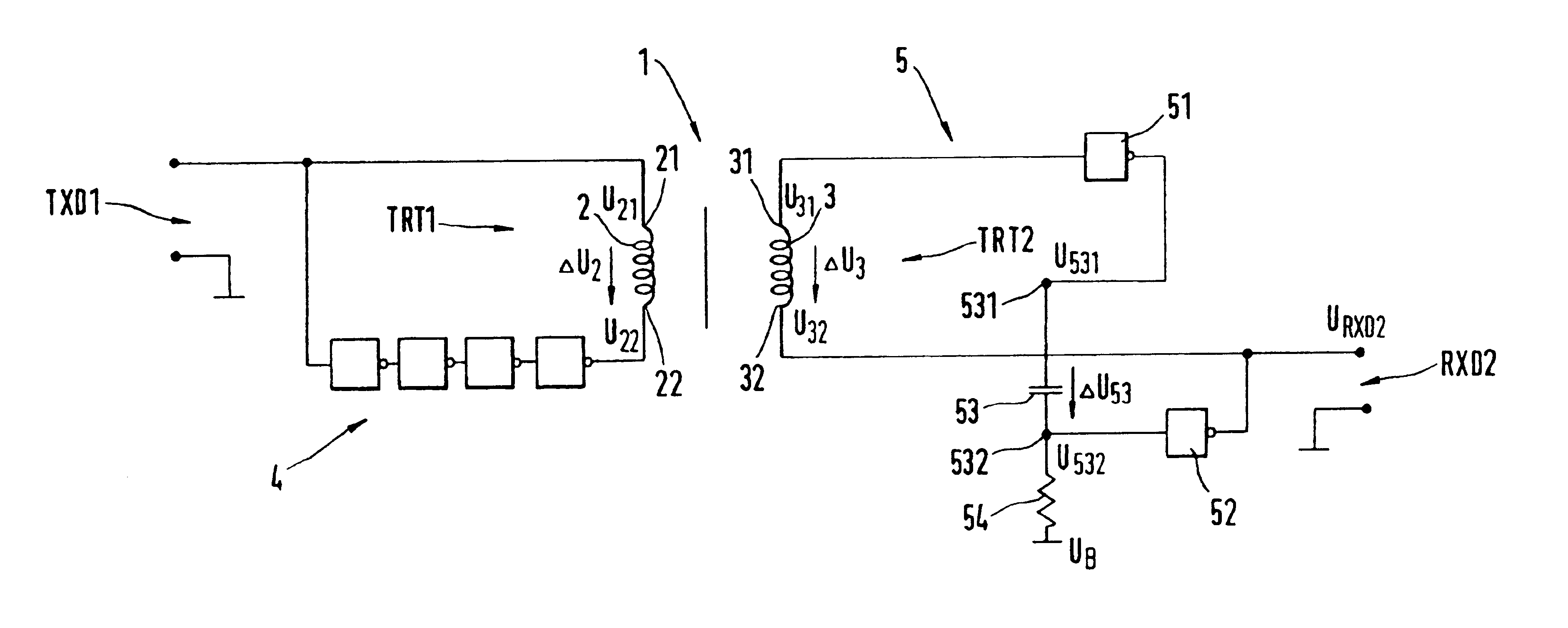
The transmission channel further comprises a first conversion stage SC1 with a coupling-signal port TRT1, a second conversion stage SC2 with a coupling-signal port TRT2, and an isolating path IP between the coupling-signal ports TRT1, TRT2, which has a predeterminable isolation capability. The isolation capability of the isolating path IP is dependent on dielectric strength ...


PUM


Abstract

For the electrically isolated transmission of digital signals, an isolating path of a channel formed by a transformer is used. The channel further includes a conversion stage for converting the digital signal to a transmissible coupling signal and a conversion stage for converting a coupling signal to the digital signal. This conversion is accomplished by a monostable multivibrator. The coupling signal is a square-wave voltage which is generated by a delay circuit in the conversion stage and is converted on the isolating path to a square-wave voltage serving as the coupling signal.

Description

BACKGROUND OF THE INVENTIONThis invention relates to a transmission channel for the electrically isolated transmission of digital signals.Prior-art transmission channels of this kind are frequently used for the transmission of digital signals by means of signal transmission lines, particularly over great distances, and serve to separate the potentials between the transmitter and receiver units of a data communications system. Such potential isolation is necessary to suppress interference signals caused by transient currents on the signal transmission lines.Because of their high efficiency, transformers are often used to provide electrical isolation. Due to the effect of the inductances of transformers, however, the use of the latter reduces the edge steepness of the digital signal, so that this method may be unsuitable. In addition, transformers also transfer electromagnetic interference introduced to them, and the suppression of such interference involves a considerable amount of t...

Claims


Application Information

Patent Timeline
Patent Type & Authority Patents(United States)
IPC IPC(8): H04B3/00
CPCH04L25/0266
Inventor KONRAD, STEPHAN
Owner KONRAD STEPHAN
Why Eureka
Try Eureka