Method and apparatus for positioning a mobile station

a mobile station and positioning method technology, applied in the field of communication systems, can solve the problems of improving positioning accuracy, affecting the accuracy of positioning, and difficulty in distinguishing direct waves from noise, so as to achieve accurate positioning of mobile stations

Inactive Publication Date: 2005-02-08
PIONEER CORP
View PDF8 Cites 39 Cited by
  • Summary
  • Abstract
  • Description
  • Claims
  • Application Information

AI Technical Summary

Benefits of technology

The present invention has been made in view of those problems inherent in the prior art, and it is an object of the invention to provide a positioning apparatus which is capable of more accurately positioning a mobile station.

Problems solved by technology

However, the foregoing conventional positioning method has a problem in that it is affected by so-called multipath fading and noise to degrade the positioning accuracy, and that it encounters difficulties in improving the positioning accuracy due to its susceptibility to such external factors.
For this reason, the conventional positioning method has a problem in that it could erroneously determine a peak of the correlation value caused by a multipath wave as a peak attributable to the direct wave.
Further, the situation as illustrated in FIGS. 6A, 6B can be encountered, in addition to the influence of the multipath waves, when the mobile station receives noise correlated to correlation data DA corresponding to the base station A, and a peak appears in a correlation value CRRA due to the nose, causing difficulties in distinguishing the direct wave from such noise.
When the propagation range LAe calculated from the position tAe at which a peak of a correlation value appears due to the multipath waves or noise is erroneously determined as the range from the base station A, a position Pe deviated from the essential position (true position) of the mobile station P is determined as the current position of the mobile station, as illustrated in FIG. 7, resulting in a degraded positioning accuracy.
While the foregoing exemplary case has been described for the case where a direct wave from the base station A cannot be accurately detected, it is possible in an actual operation that a direct wave cannot be accurately detected due to disturbance such as multipath waves for the remaining base stations B, C. This makes an improvement in positioning accuracy more difficult.
However, under an actual communication environment in which detected range values from the base stations A, B, C to the mobile station P include randomly varying errors due to the influence of multipath fading and noise, the conventional positioning method could erroneously recognize a variety of positions within a hatched region shown in FIG. 7 as the current position of the mobile station

Method used


Image

  • Method and apparatus for positioning a mobile station
  • Method and apparatus for positioning a mobile station
  • Method and apparatus for positioning a mobile station

Examples


first embodiment

In the following, the present invention will be described.

FIG. 8 is a diagram schematically representing the general configuration of a mobile communications system which utilizes a broadband CDMA (Code Division Multiple Access) scheme, one type of spread spectrum (SS) scheme, wherein a hexagonal cell based zone organization method is shown as one example. For reference, a zone refers to an area in which radio waves from a base station can reach, and the zone organization method refers to a method which involves assigning a plurality of predetermined frequencies to base stations in respective zones and relying on the zones to closely cover a whole communication service area.

Specifically, in the mobile communications system according to the first embodiment, the communication area has been previously partitioned into a plurality of hexagonal zones called “cells.” A base station is installed in each cell, and is designed such that each cell extends over a range in which radio waves ca...

second embodiment

(Second Embodiment)

Next, a second embodiment of the present invention will be described. For reference, the second embodiment relates to a modified embodiment of the positioning apparatus 10 described in the first embodiment.

The mobile station of the second embodiment is similar in configuration to the mobile station 10 of the first embodiment illustrated in FIGS. 9 through 11. Also, since the positioning processing is performed based on the principles similar to the positioning principles described with reference to FIGS. 11 and 12A through 12C, description on the configuration and positioning principles of the mobile station in the second embodiment is omitted.

However, the mobile station in the second embodiment operates in accordance with the positioning processing illustrated in FIG. 23 instead of the positioning processing illustrated in FIGS. 15 through 21 in the positioning processing steps of the positioning apparatus 10 in the first embodiment described with reference to FI...

third embodiment

(Third Embodiment)

Next, a third embodiment of the present invention will be described with reference to FIGS. 24-27.

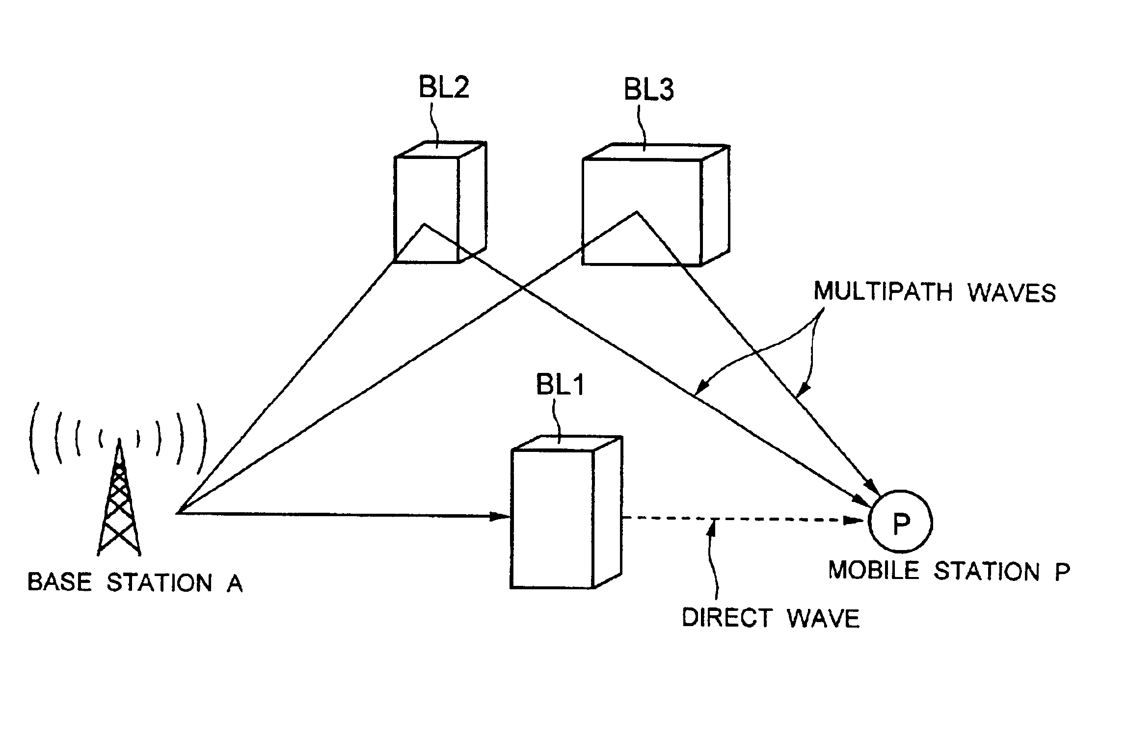
In the aforementioned first and second embodiments, the positioning apparatus 10 of the mobile station receives incoming radio waves from base stations to determine its own current position (xp, yp). On the other hand, the third embodiment, described below, is such that base stations determine the current position (xp, yp) of a mobile station to accomplish highly accurate positioning which suppresses the influence of multipath fading, noise and the like.

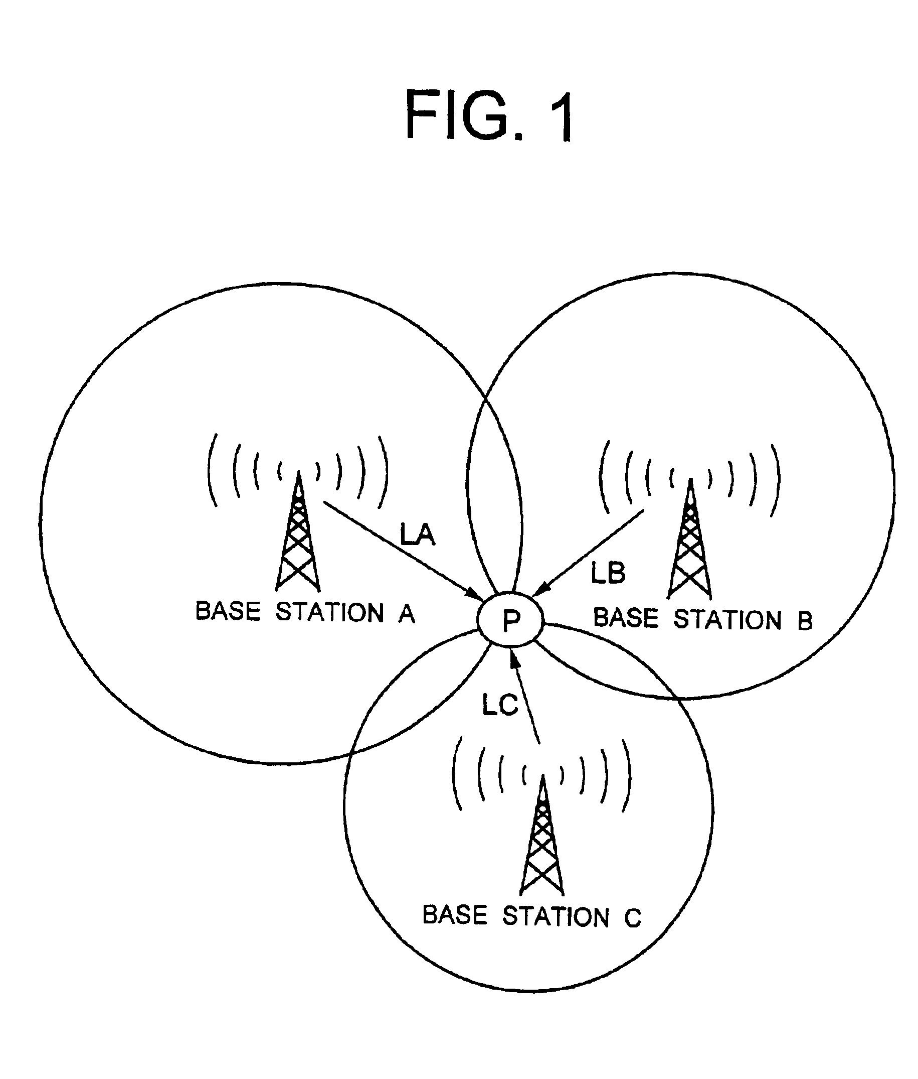
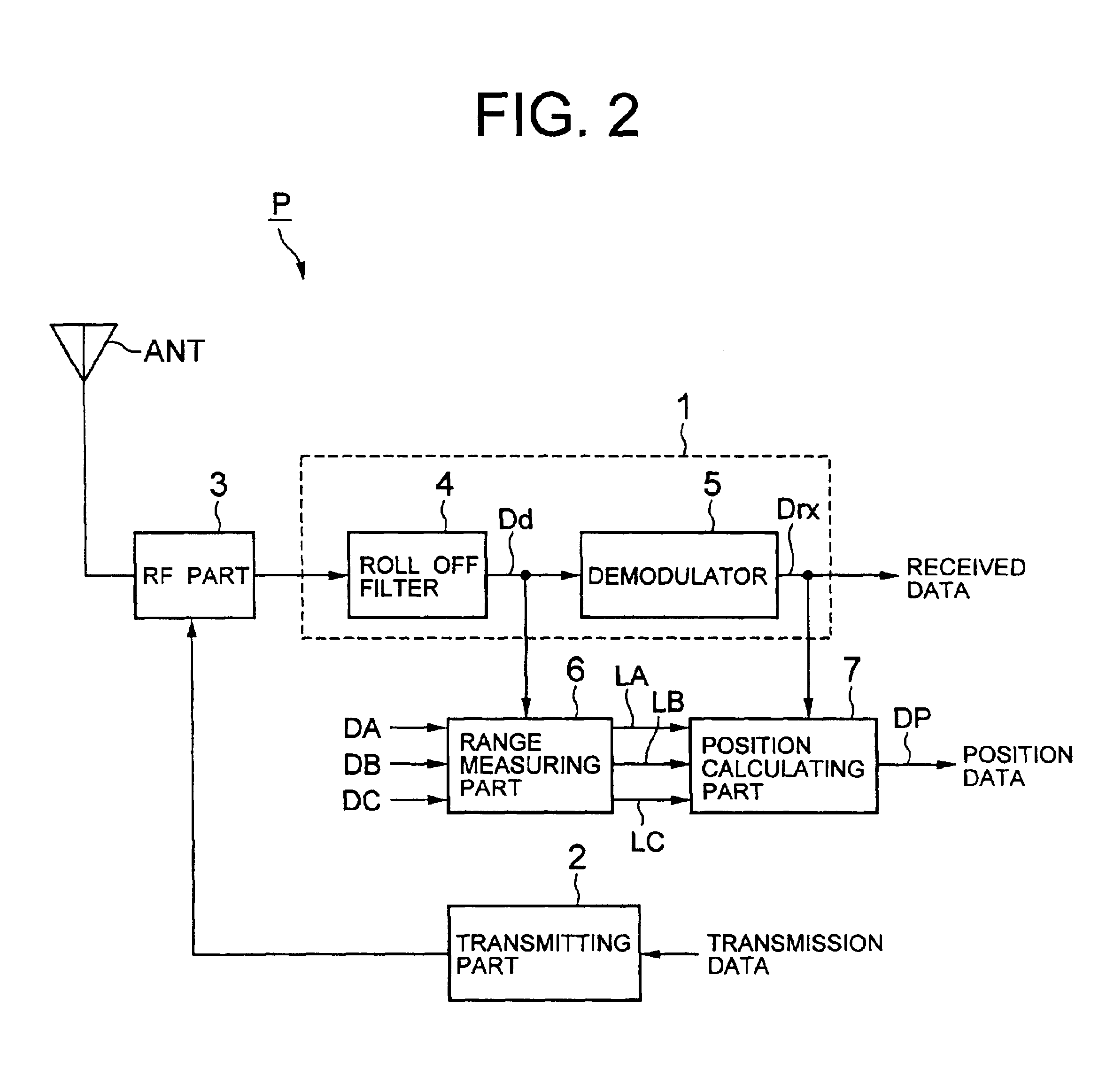
Specifically, according to the third embodiment, as schematically illustrated in FIG. 24, as a mobile station 10 transmits a radio wave for requesting positioning (hereinafter called the “positioning radio wave”) at an arbitrary position within a communication area, base stations A, B, C, for example, located around the mobile station 10 receive this positioning radio wave. Then, each of the base stations A, B, C and a ...


PUM


Abstract

A positioning apparatus and method for accurately determining a current position of a mobile station. The current position of the mobile station is determined utilizing radio waves arriving from a plurality of base stations installed in a communication area. For calculating a propagation range of a radio wave arriving from each base station, error correction processing is performed using a predetermined error correction coefficient previously calculated by measuring a radio wave propagation situation around each base station to estimate a propagation range of a direct wave within incoming radio waves. The current position of the mobile station is determined using the estimated propagation range and the positions of the respective base station.

Description

BACKGROUND OF THE INVENTION1. Field of the InventionThe present invention generally relates to a communications system which utilizes radio communications, and more particularly, to positioning method and apparatus for detecting the position of a mobile station such as a portable telephone.2. Description of Related ArtIn recent years, communications systems utilizing radio communications have been rapidly popularizing, and further progress is expected, for example, in such fields as mobile communications systems such as portable telephones and pagers, navigation systems for detecting the position of a moving person or vehicle, and the like.For promoting the further progress of such communications systems, the development is desired for a positioning apparatus which is capable of accurately determining the position of a mobile station such as a movable portable telephone, navigation apparatus and the like, establishing a stable communication state between a base station and the mobil...

Claims


Application Information

Patent Timeline
Patent Type & Authority Patents(United States)
IPC IPC(8): G01S1/00G01S1/02G01S5/02G01S5/14H04M3/42H04W64/00
CPCG01S5/021G01S5/0215G01S5/0273G01S5/14G01S5/0278G01S5/145G01S5/0218
Inventor SHIODA, TAKEHIKONOHARA, MANABU
Owner PIONEER CORP
Why Eureka
Try Eureka