GPS navigation apparatus

a navigation apparatus and GPS technology, applied in navigation instruments, traffic control systems, instruments, etc., can solve the problems of complicated and troublesome route creation operation, containing useless routes between the start point and the destination,

Inactive Publication Date: 2005-02-08
VERTEX STANDARD
View PDF10 Cites 119 Cited by
  • Summary
  • Abstract
  • Description
  • Claims
  • Application Information

AI Technical Summary

Benefits of technology

The present invention is created with an object to provide a GPS navigation apparatus having a new function, provided thereon, which is capable of automatically cre

Problems solved by technology

The route preserved by use of the tracking function as described above often contains useless routes between the start point and the destination.
Specifically, although a procedure to execute is that the start points, specific points and destinations are selected one by one on a point listed picture screen of the tracking function, and the selected data is transferred to established information in the routing function in the conventional model, there is a recent model which can register as many as 600 points, and when a multiplicity of t

Method used


Image

  • GPS navigation apparatus
  • GPS navigation apparatus
  • GPS navigation apparatus

Examples


embodiment 1

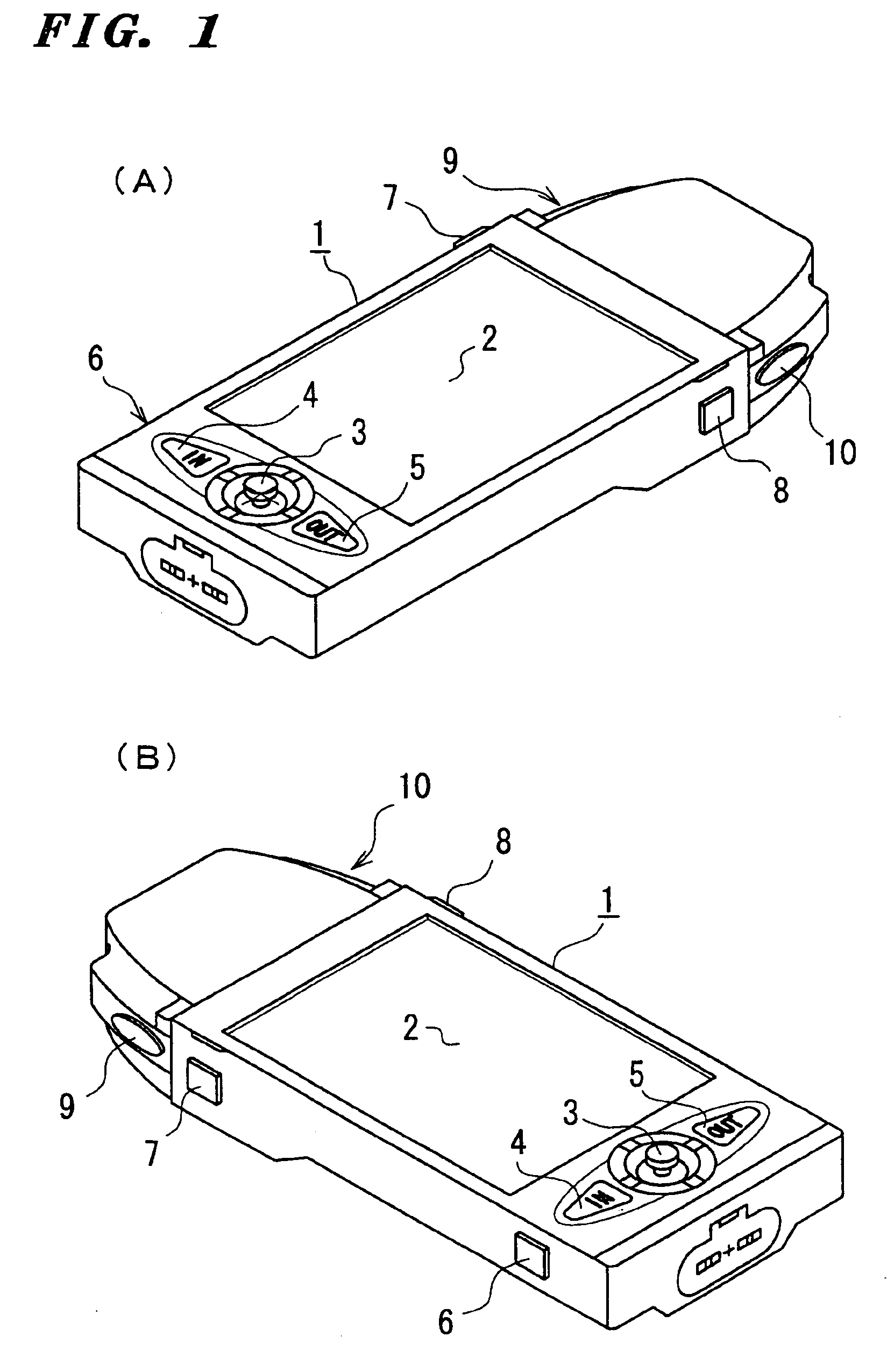
Firstly, FIGS. 1(A) and 1(B) are external perspective view, looked from the upside right and the upside left, respectively, of a GPS navigation apparatus relating to the embodiment.

A liquid crystal display unit (LCD) 2 is provided in the front of the apparatus 1, and a STICK key 3, an IN-key 4, and an OUT-key 5 are provided downside thereof, and a POWER key 6, a MENU key 7, a SAVE key 8 of a battery, and two PAGE keys 9, 10 are provided on the right and left sides thereof.

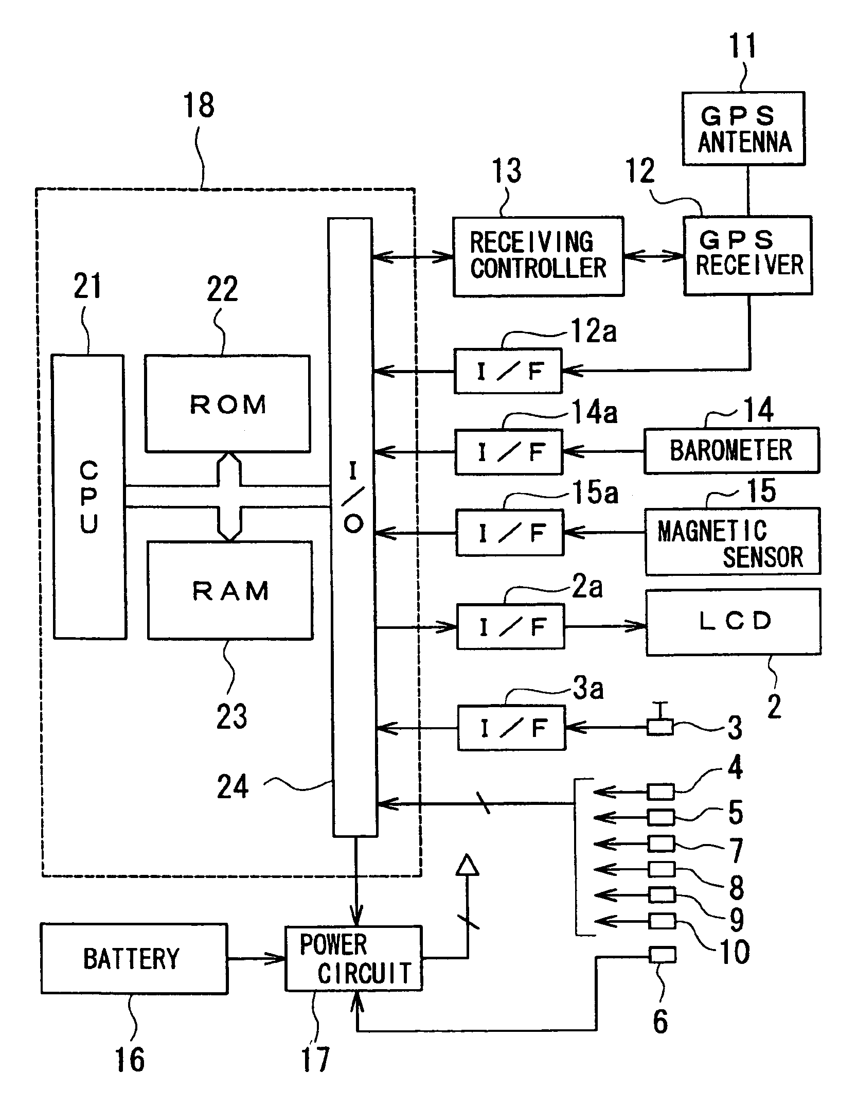
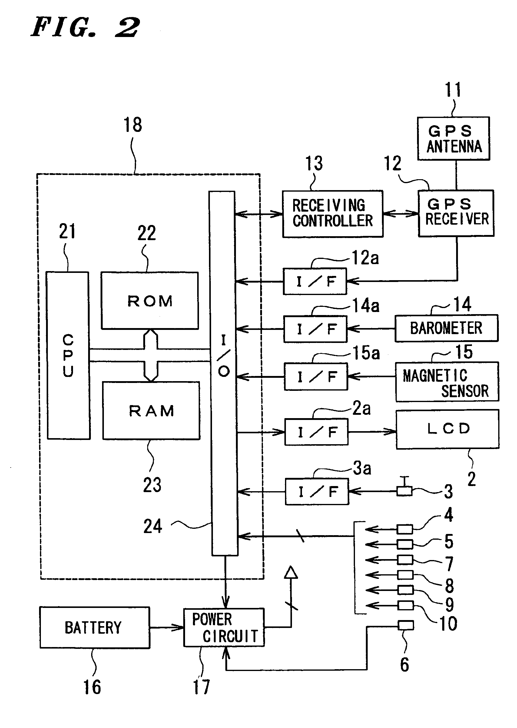
Then, a system circuit as shown in FIG. 2 is incorporated as a print wiring substrate or a module in a housing of the apparatus.

In FIG. 2, shown are a GPS antenna 11, a GPS receiver 12, a receiver controller 13 for controlling the receiver 12, a barometer 14, a geomagnetism sensor 15, a battery 16, a power source circuit 17, and a microcomputer circuit 18.

Here, the microcomputer circuit 18 has an ordinary configuration composed of a CPU 21, a ROM 22, a RAM 23, and an I / O port 24. A received signal by the GPS receiv...

embodiment 2

Although the ROUTE provided in the above-described first embodiment is constructed by connecting the WAY-POINTs or MARK-POINTs located between the START POINT and the DESTINATION POINT by straight line, sequence for connecting the WAY-POINTs or MARK-POINTs is in accordance with the establishing sequence (time series sequence) in the tracking function. Accordingly, the ROUTE thereof is not always the shortest.

When the track obtained by the tracking function is more remarkably meandered than the case of FIG. 7 as shown in FIG. 15, the ROUTEs are constructed using the WAY-POINT and MARK-POINT as objectives with the routing function as shown in FIG. 16 and FIG. 17, respectively. However, the ROUTEs are not the shortest, and the ROUTEs shown in FIG. 18 and FIG. 19 correspond to the shortest routes.

On the other hand, in both cases returning from the DESTINATION POINT to the START POINT and going from the START POINT to the DESTINATION by use of the ROUTE registered later, the navigation i...


PUM


Abstract

In a GPS navigation apparatus, a procedure of preparation of route for navigation using a specific point (WAY-POINT or MARK-POINT) established and registered by the tracking function is simplified. A TRACK list picture is read out from a MENU picture by the predetermined operation, and a desired TRACK name is designated from the list. When a type the specific point is selected by the predetermined operation to designate conversion from the TRACK to a ROUTE, position data of the START POINT, the specific point of the selected type, and the DESTINATION POINT, of the designated TRACK name are extracted, and interpolation data connecting the positions by straight line in the time series sequence is produced to construct a ROUTE for navigation. Conventionally, the selection has been made by each POINT unit, however, an automatic conversion in a batch in a TRACK unit is employed, and thus a route creating operation is extremely simplified.

Description

BACKGROUND OF THE INVENTION1. Field of the InventionThe present invention relates to a GPS navigation apparatus, and in particular relates to improvement in a function when a new route is created by use of point data, which has been specifically inputted by an operator to be stored as tracking data, together with movement locus data sequentially obtained in a tracking mode.2. Description of the Related ArtA two-dimensional or three-dimensional positioning system using a radio wave from a GPS (global positioning system) satellite has been developed, and widely used as a navigation apparatus for automobiles, vessels, or the like. The GPS navigation apparatus is, together with an intrinsic navigation function, provided at least with a tracking function and a routing function.Here, the tracking function is a function for displaying a movement state as locus information while positioning it at an interval of unit distance or unit time, and for preserving the locus data recorded from the ...

Claims


Application Information

Patent Timeline
IPC IPC(8): G01C21/20G01C21/00G09B29/00G08G1/00G08G1/0969G09B29/10
CPCG01C21/20
Inventor MIWA, YOHEI
Owner VERTEX STANDARD
Why Eureka
Try Eureka