Multi-bit test circuit

a multi-bit test and test circuit technology, applied in the field of multi-bit test circuits, can solve the problems of wasting time, wasting time, and wasting time in executing the test, so as to reduce the interconnection line length of teacher data, reduce the driven load of teacher data, and accelerate timing

Inactive Publication Date: 2005-02-08
RENESAS ELECTRONICS CORP
View PDF8 Cites 10 Cited by
  • Summary
  • Abstract
  • Description
  • Claims
  • Application Information

AI Technical Summary

Benefits of technology

[0016]Another object of the present invention is to provide a multi-bit test circuit that can perform determining operations at a faster timing with reduced interconnection line length of teacher data.
[0017]Further another object of the present invention is to provide a multi-bit test circuit which can reduce the driven load by teacher data.
[0021]Applying a plurality of data bit pairs containing different teacher data from each other to the first determining circuits eliminates the need of applying 1-bit specific teacher data to the remaining bits, thereby reducing the load of teacher data. Hence, it becomes unnecessary to provide a buffer for driving teacher data, so as to reduce the layout area of the multi-bit test circuit.

Problems solved by technology

When the readout data match the expected data, the semiconductor memory device is considered to operate properly, and on the other hand, when they mismatch each other, the semiconductor memory device is considered to contain a bit defect.
It would take too much time to execute this checking test on a semiconductor memory device with a large storage capacity on a bit by bit basis.
This high level of the FLAG indicates a mismatch in logical level among the memory cell data, thereby detecting the presence of a bit failure.
This causes a problem that a large chip area is needed for the multi-bit test circuit.
This interconnection of the teacher data causes another problem that the propagation delay of the output signal of buffer circuit BF may delay the defining timing, to make it unable to drive flag FLAG to the definite state condition quickly.
In order to avoid this problem, buffer circuit BF must have a larger driving power, causing further problem of occupying even larger chip area.

Method used


Image

  • Multi-bit test circuit
  • Multi-bit test circuit
  • Multi-bit test circuit

Examples


first embodiment

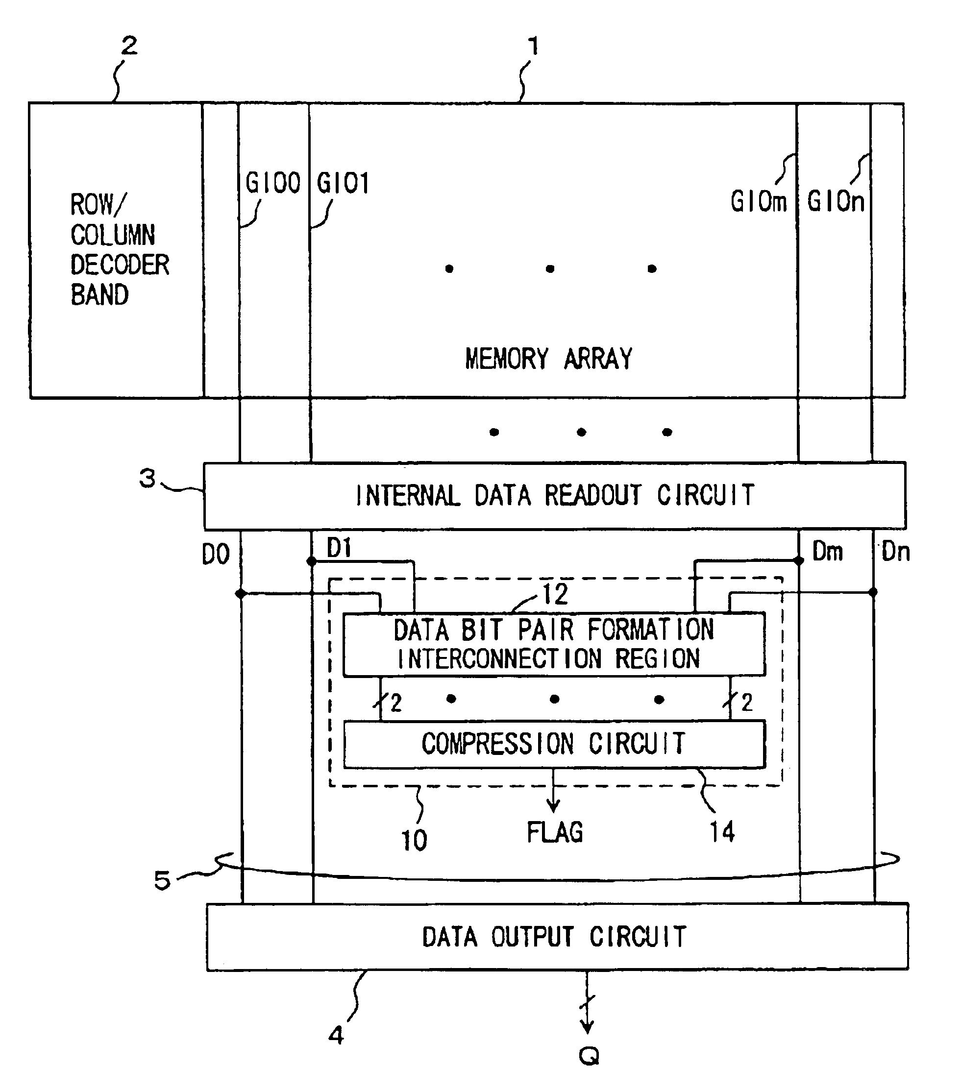
[0031]FIG. 1 is a diagram schematically showing the structure of a main part of the semiconductor memory device according to the present invention. In FIG. 1, the semiconductor memory device includes a memory array 1 having a plurality of memory cells arranged in rows and columns, and a row / column decoder band 2 for selecting a row of and a column of the memory cells in memory array 1. In row / column decoder band 2, row decoders for selecting a memory cell row in memory array 1, and column decoders for selecting a memory cell column in memory array 1 are placed in alignment with each other. In memory array 1, word lines arranged corresponding to the memory cell rows, and column selecting lines transmitting a column selection signal for selecting a memory cell column are arranged along the direction of rows.

[0032]Over memory array 1, global data line pairs GIO0-GIOn are arranged to transmit internal data.

[0033]The selected columns of memory array 1 are connected to these global data l...

second embodiment

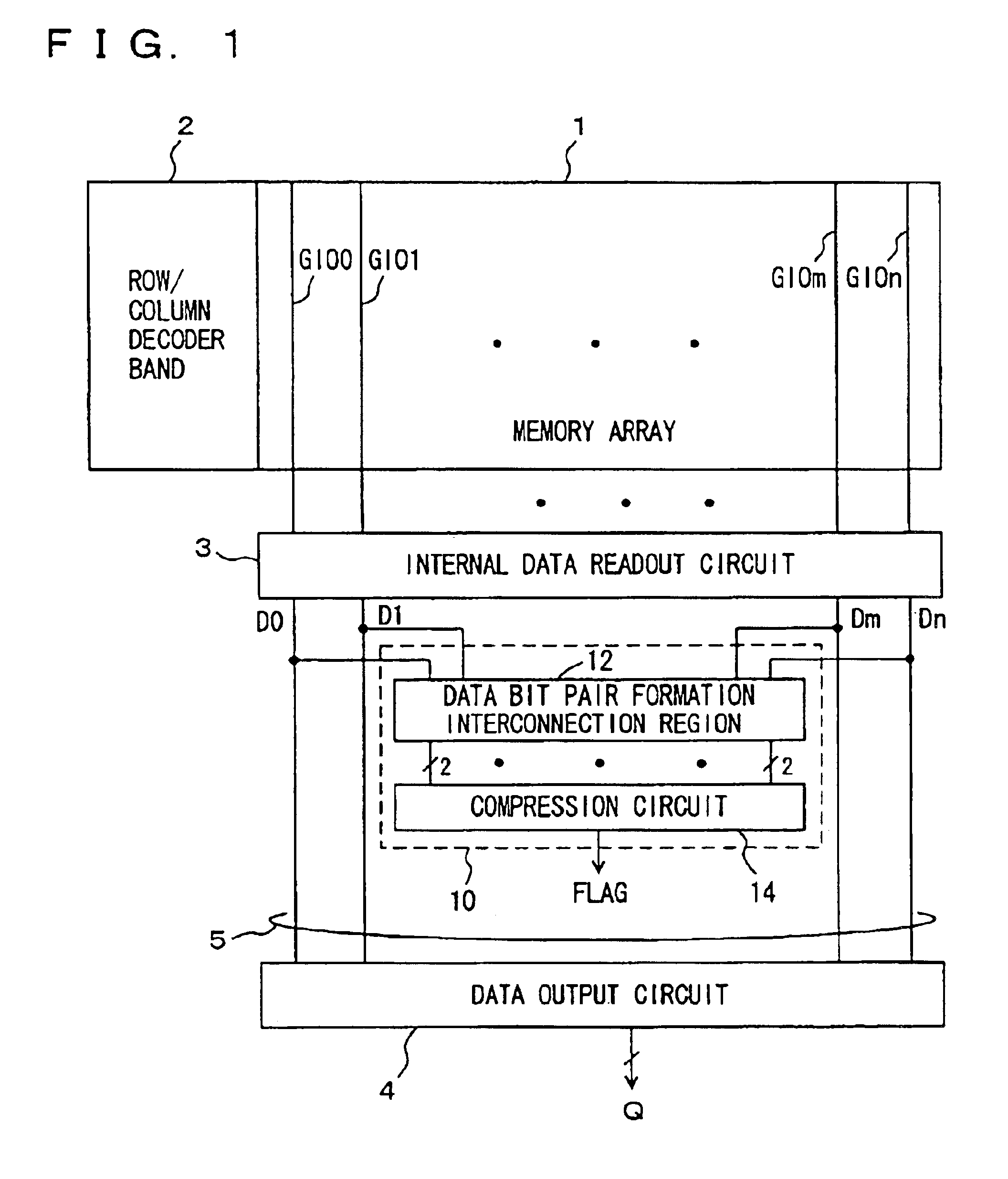
[0041]FIG. 2 shows the structure of multi-bit test circuit 10 according to the second embodiment of the present invention. Multi-bit test circuit 10 shown in FIG. 2 handles 32-bit readout data DOUT0>-DOUT31>. These readout data bits DOUT31:0> correspond to data bits D0-Dn or a part of them shown in FIG. 1.

[0042]Data DOUT0>-DOUT31> are divided into four data groups IOG0-IOG3 each having 8-bit data. In data bit pair formation interconnection region 12 of multi-bit test circuit 10, internal interconnection lines L0-L23 are so arranged that data bits in the same positions in adjacent data groups make pairs. For example, as shown in FIG. 2, internal interconnection line L0 is so arranged that data bit DOUT0> having the smallest number in data group IOG0 is paired up with readout data bit DOUT8> having the smallest number in adjacent data group IOG1. Internal interconnection line L7 pairs up internal readout data bit DOUT7> with readout data bit DOUT15> in adjacent data group IOG1.

[0043]I...

third embodiment

[0051]FIG. 3 schematically shows the structure of multi-bit test circuit 10 according to the third embodiment of the present invention. In multi-bit test circuit 10 shown in FIG. 3, EXOR gates XR24-XR31 are provided corresponding to readout data bits DOUT24>-DOUT31>, respectively, in addition to the structure of multi-bit test circuit 10 shown in FIG. 2. As the teacher data bits for readout data bits DOUT24>-DOUT31>, readout data bits DOUT0>-DOUT7> in data group IOG0 adjacent in the cyclic manner are transmitted to EXOR gates XR24-XR31 via internal interconnection lines L24-L31, respectively.

[0052]The output signals of EXOR circuits XR0-XR31 are applied to OR circuit OGA so as to be compressed finally to 1-bit flag FLAG.

[0053]The relation between data bits DOUT23:0> and the teacher data is the same as in the second embodiment, so that the corresponding components are referred to with the same reference numerals, and their detailed description will be omitted.

[0054]In the structure o...


PUM


Abstract

Internal read out data bits are divided into a plurality of data groups, and data bits in corresponding positions in different data groups are paired off. A determination gate is provided to each pair of data bits, and determining operation is performed in each pair to compress the result of determination to finally generate a 1-bit flag indicating a match / mismatch in logic level among the internal read out data. Consequently, a multi-bit test circuit that has a reduced layout area and can perform high-speed multi-bit determination is provided.

Description

BACKGROUND OF THE INVENTION[0002]1. Field of the Invention[0003]The present invention relates to a multi-bit test circuit for carrying out tests on a plurality of memory cells at the same time, and more specifically, to a multi-bit test circuit for determining a match or a mismatch in logical level among the data bits read out in parallel from the plurality of memory cells.[0004]2. Description of the Background Art[0005]One of the tests applied to a semiconductor memory device is a checking of seeing if data can be written to and read from memory cells correctly. In this checking, test data having a predetermined bit pattern are written in memory cells, then read therefrom, and then it is determined whether the read out data are matched with expected value data. When the readout data match the expected data, the semiconductor memory device is considered to operate properly, and on the other hand, when they mismatch each other, the semiconductor memory device is considered to contain...

Claims


Application Information

Patent Timeline
Patent Type & Authority Patents(United States)
IPC IPC(8): G11C29/40G11C29/34G11C29/04G01R31/3185G01R31/28
CPCG11C29/40G11C29/34
Inventor KINOSHITA, MITSUYADOSAKA, KATSUMI
Owner RENESAS ELECTRONICS CORP
Why Eureka
Try Eureka