Panel connector system

a panel connector and connector technology, applied in the field of panel connector systems, can solve the problems of wittier system not providing the panel face of adjacent panels, deformation and damage of channel walls, and inability to connect, so as to reduce the lateral stress of sidewalls, eliminate any spaces or gaps, and replace easily and quickly

Inactive Publication Date: 2005-02-15
SKYLINE DISPLAY LLC
View PDF8 Cites 14 Cited by
  • Summary
  • Abstract
  • Description
  • Claims
  • Application Information

AI Technical Summary

Benefits of technology

Another feature and advantage of the invention is that the cooperating seating surfaces of the connectors that provide the forces to secure the abutted panels together are normal to the planes of the panels thereby minimizing lateral stresses on sidewalls of the channel portions.
Another feature and advantage of the invention is that apertures or cutaway portions are utilized to create plastic spring members that provide bias to urge cooperating connectors and the attached panels together.
Yet another feature of this invention is that the present panel system may be set up and taken down without the use of tools.
Sti

Problems solved by technology

This can result in deformation and damage to the channel walls.
Once such damage occurs the connection is compromised visually in that a gap may be visible, and also compromised form a structural perspective, that is, the connection may be loose and insecure.
The Wittier system does not provide for panel faces of adjacent panels that directly adjoin to provide a substantially continuous fac

Method used


Image

  • Panel connector system
  • Panel connector system
  • Panel connector system

Examples


second embodiment

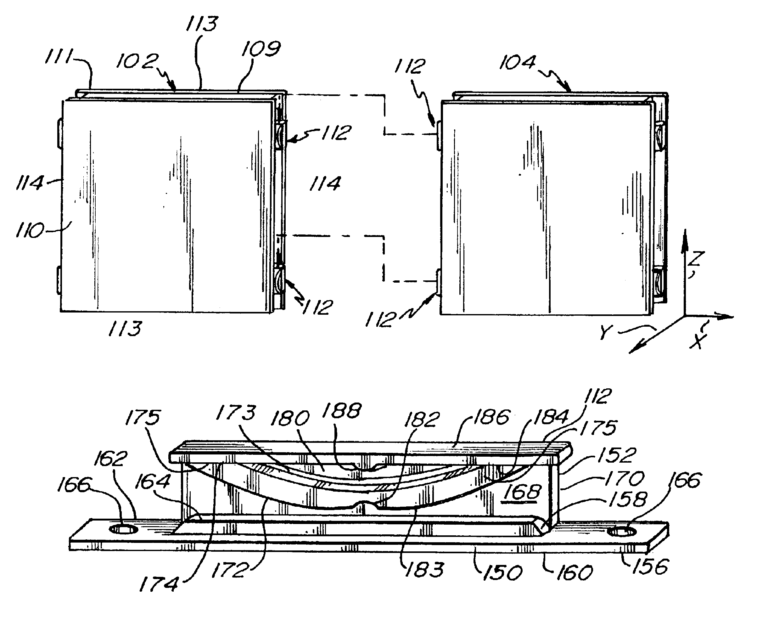
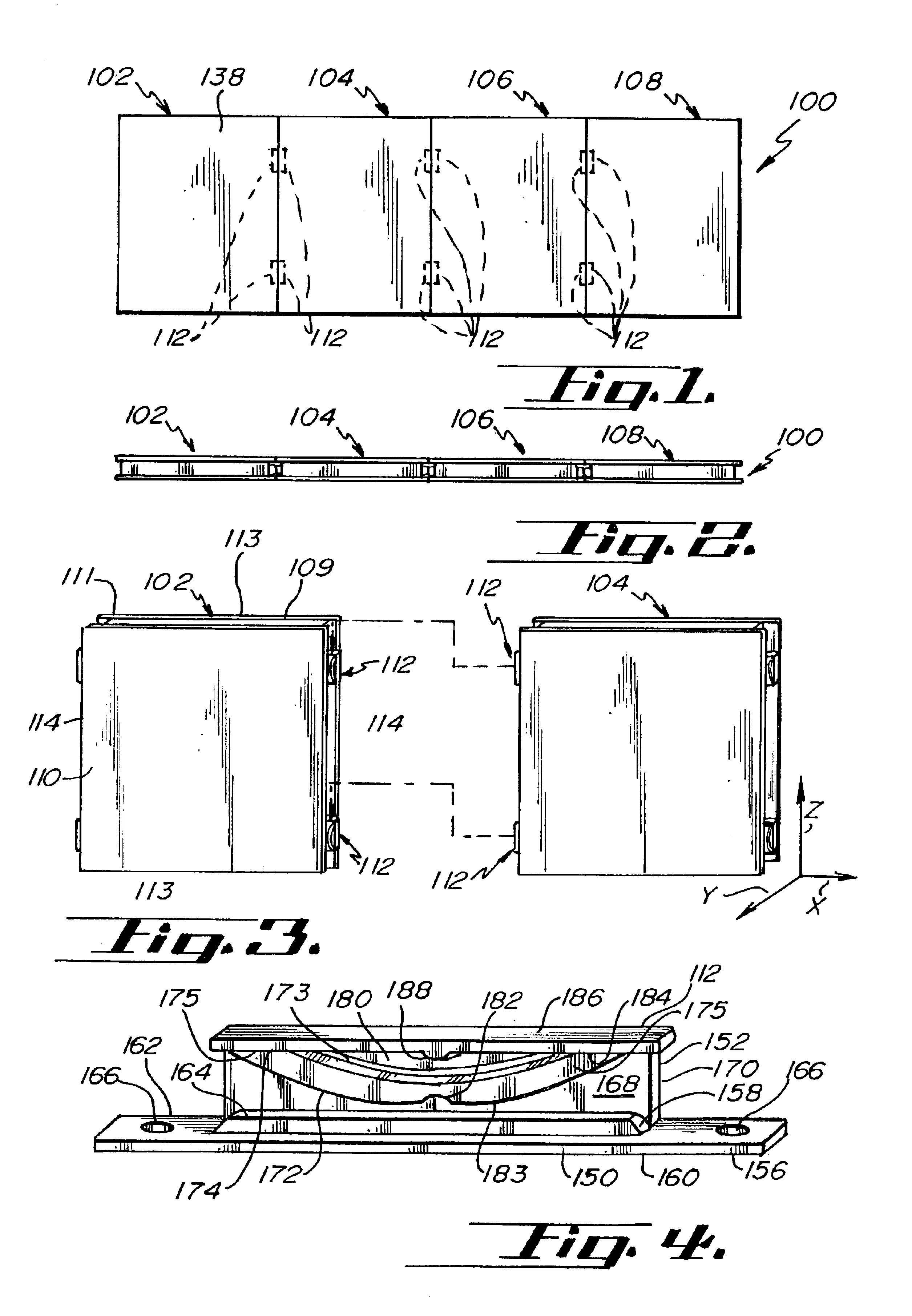
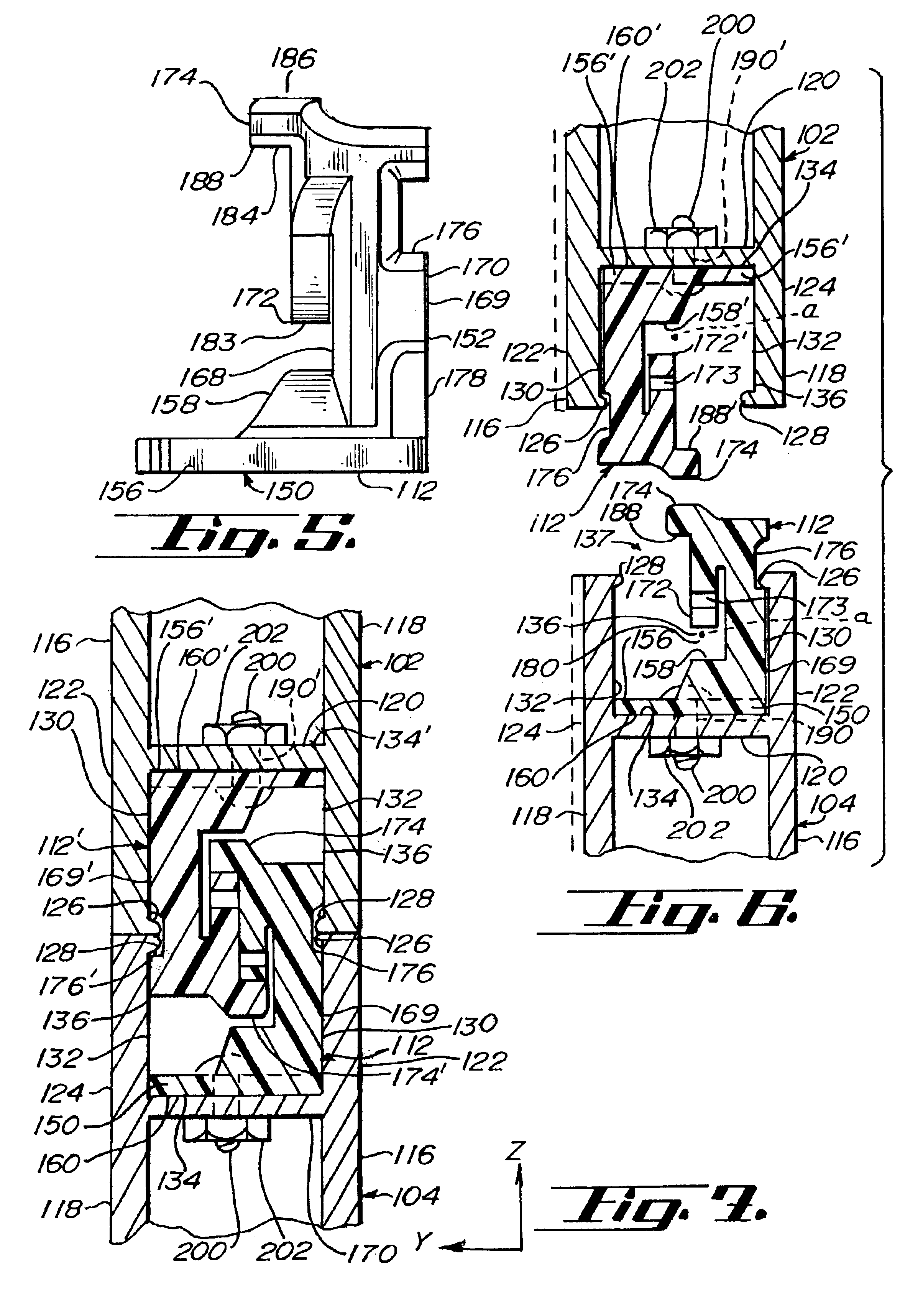
FIGS. 9 and 10 depict the present connector, indicated generally by the numeral 212. The connector 212 is generally unitary in construction in this embodiment but may be considered to include respective base and arm portions 214 and 216. The base member 214, in turn, may be considered to include a plate 220 and an arcuate contact element 222. The plate 220 displays respective inboard and outboard surfaces 224 and 226 and may have a plurality of laterally disposed bolt holes 228. The contact element 222 arches or curves away from the base plate 220 in this embodiment and displays an outboard surface 230.

The arm portion 216 displays respective first and second surfaces 232 and 234 and may be considered to include a transverse extension 236, a biasing element 238, and an axial ledge 240. A generally longitudinal (axial) slot 242 and a plurality of ribs 244 are defined from second surface 234. The biasing element 238 extends arcuately from peripheral connection points to the ledge 240 a...

third embodiment

FIG. 11 depicts the present connector by the numeral 312. Connector 312 is generally unitary in this embodiment, but may be considered to include a base member 314 and a arm portion 316. The base member 314 displays respective inboard and outboard surfaces 324 and 326 and defines a plurality of bolt holes 328. The arm portion 316 displays respective first and second surfaces 332 and 334 (not shown). A resilient biasing element 338 extends from a ledge 340 and a slot 342 is generally longitudinally defined and extends from the second surface 334 in this embodiment. In this embodiment, the ledge 340 extends only through a portion of the outboard surface 350. Also in this embodiment, only one end of the biasing element 338 is attached to the ledge 340. The other end of the biasing element 338 is unattached. The connector 312 also differs from the previous embodiments in that a contact element, such as contact elements 158 or 222, is absent.

The connector 312 is disposed in a panel chann...


PUM


Abstract

A panel connector system is provided and includes a plurality of panels and panel connectors. Each panel includes panel sidewall extensions, lips extending from the sidewall extensions, and cross-walls. The sidewall extensions, lips, and cross-walls define outwardly opening edge channels. The panel connectors include a base and a member extending generally transversely from the base. The base includes a base plate and a contact element. The arm portion includes a generally longitudinal slot, a ledge or protruding portion and a spring portion. A male seating surface extends from the ledge and a female seating surface is present on the spring portion. The clip base plate is fastened to the panel cross-wall and one of the lips is disposed in the clip slot when the clip is attached within the edge channel. Two panels are reversibly connected by raising one of the panels and vertically aligning and lowering one of the edges of the raised panel with one of the edges of the other panel, thereby slidably and vertically mating the fastened connectors. When the connectors are mated, the biasing elements are slidingly resiliently biased toward the connector ledges, the male seating surfaces is disposed on the female seating surface, and adjacent lips of joined panels are disposed in the connector slot.

Description

BACKGROUND OF THE INVENTION1. Field of the InventionThe present invention relates generally to display panels and, in particular, the present invention relates to devices for connecting display panels.2. Background of the InventionDisplay panel systems are widely used in reception areas, trade shows, museums, art exhibits, academic and research society meetings, and the like where displays or visual information is temporarily displayed or where physical space barriers are desired. The faces of these panels may be rigid or may incorporate soft materials (e.g., cork) or magnetic materials for temporarily attaching the visual information to the panels. It is desirable that panel systems may be quickly and easily assembled and disassembled to accommodate a variety of display sizes and configurations, for storage, and for transportation to another site. It is also desirable that these display panels be securely connected so that the panels do not separate during use and so that they form...

Claims


Application Information

Patent Timeline
IPC IPC(8): E04B1/61
CPCE04B1/6162E04B1/6179Y10T403/65
Inventor GIMPEL, DIXONCOTA, TIMOTHYFUNK, WILLIAM
Owner SKYLINE DISPLAY LLC
Why Eureka
Try Eureka