Gas-barrier synthetic resin vessel, device for producing the same, and article-received gas-barrier synthetic resin vessel

a gas-barrier and synthetic resin technology, which is applied in the field of synthetic resin containers, can solve the problems of the outer diameter of the inner electrode and the inability to form a substantially uniform dlc film on the outer wall of the container, and achieve the effect of eliminating any adverse effects and preventing deformation

Inactive Publication Date: 2005-02-15
NISSEI ASB MASCH CO LTD
View PDF11 Cites 6 Cited by
  • Summary
  • Abstract
  • Description
  • Claims
  • Application Information

AI Technical Summary

Benefits of technology

A metal cover may be double-seamed with the flange defining the opening portion onto the container. This is because the metal cover can secure the gas barrier properties. In this case, the flange with which the metal cover is double-seamed may be coated with the DLC film or not. This is because the metal cover provides the gas barrier properties

Problems solved by technology

When the container is a so-called narrow mouth container, however, the outside diameter of inner electrode is too small relating to the diameter of container body portion, even if the in

Method used


Image

  • Gas-barrier synthetic resin vessel, device for producing the same, and article-received gas-barrier synthetic resin vessel
  • Gas-barrier synthetic resin vessel, device for producing the same, and article-received gas-barrier synthetic resin vessel
  • Gas-barrier synthetic resin vessel, device for producing the same, and article-received gas-barrier synthetic resin vessel

Examples


first embodiment

PET Can and PET Can Filled with Beer

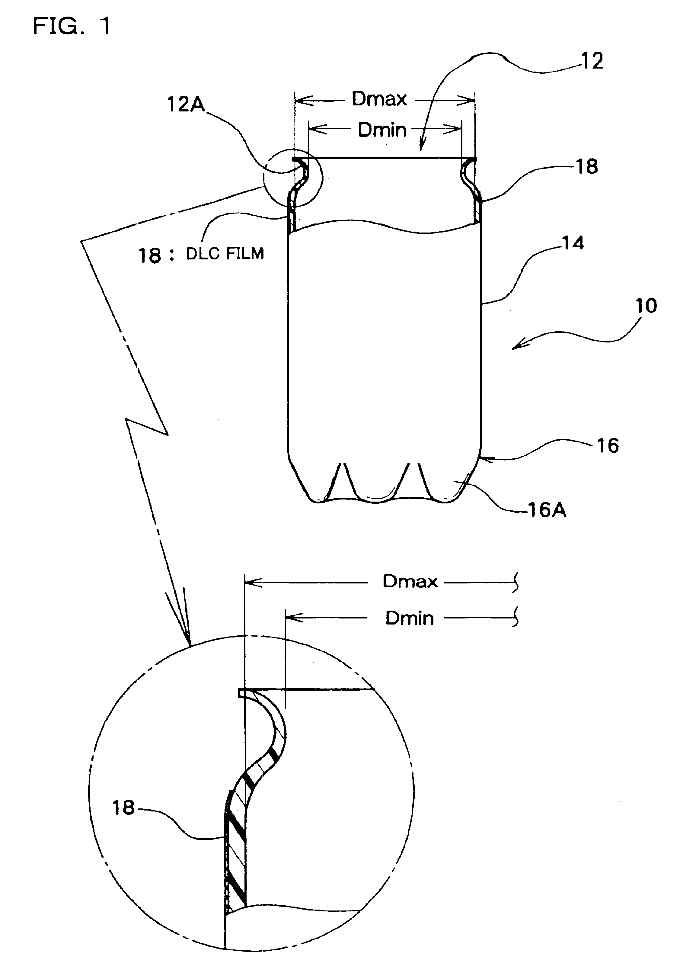
FIG. 1 shows a gas barrier synthetic resin container 10 such as PET can. The container 10 has an opening portion 12, a body portion 14 having the opening portion 12 and a bottom portion 16 for closing the end of the body portion 14.

The opening portion 12 is formed with an outwardly extending thin-walled flange 12A. The bottom portion 16 has a self-supporting structure having five legs 16A, for example.

The minimum inside diameter Dmin of the opening portion 12 is smaller than the maximum inside diameter Dmax of the body portion 14. The difference between the minimum inside diameter Dmin of the opening portion 12 and the maximum inside diameter Dmax of the body portion 14 is equal to or smaller than 20 mm. This provides a so-called wide mouth container 10.

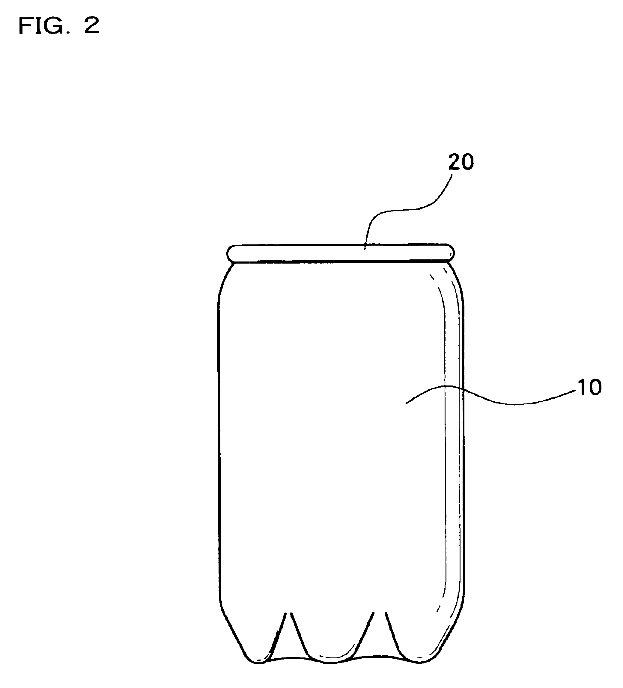
FIG. 2 shows a PET beer can 30 provided by filling the container 10 with beer before double-seaming a metal can cover 20 (of aluminum, for example) to the flange 12A.

Referring to FIGS. 1 and 2, a D...

second embodiment

FIG. 4 shows a machine different from that of FIG. 3. Parts similar in function to those of FIG. 3 are denoted by similar reference numerals and will not further be described.

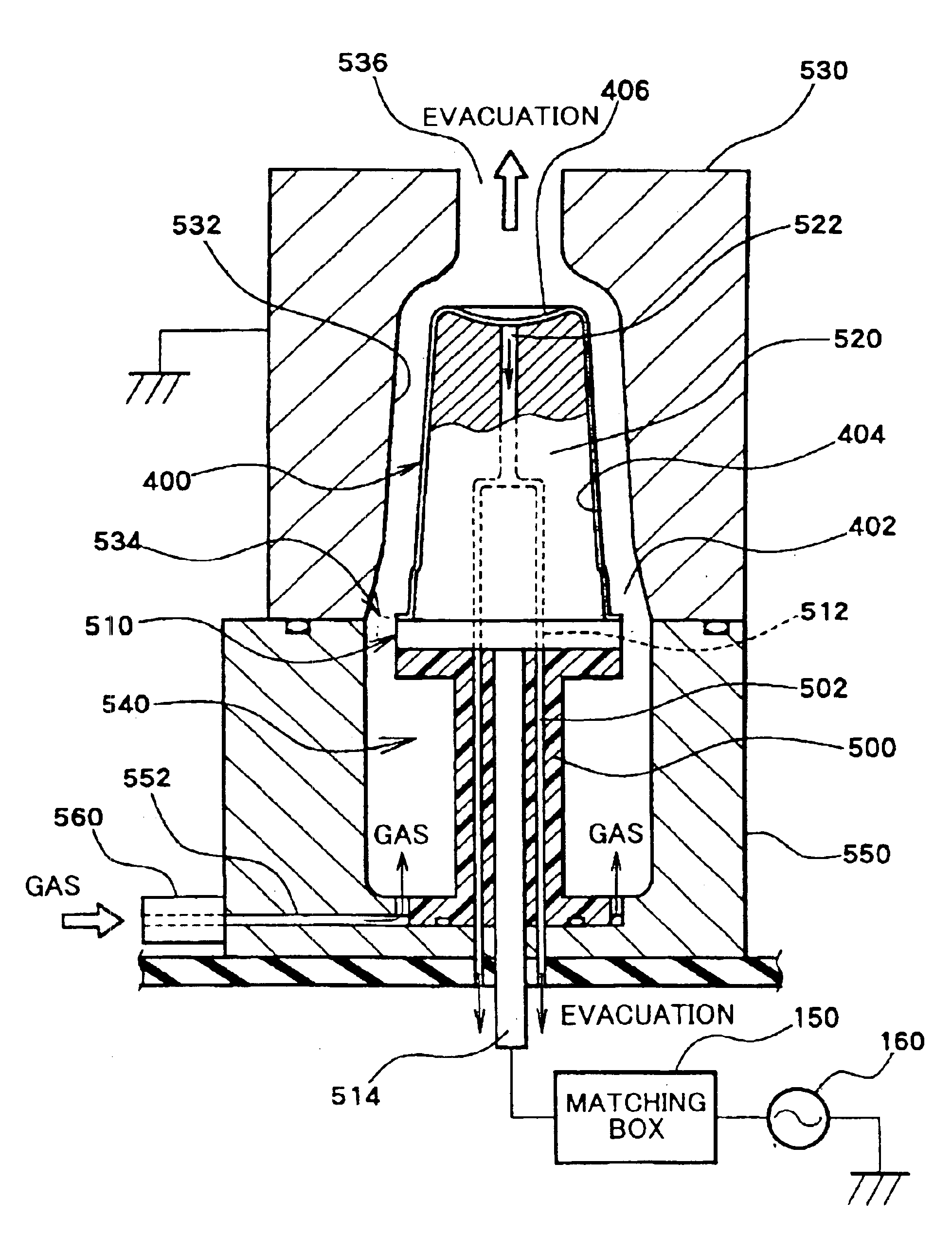
Referring to FIG. 4, the source of high-frequency power 160 is connected to an external electrode 200 through the matching box 150 while the inner electrode 220 is grounded through an electrifying shaft 222. In such an arrangement, the outer electrode 200 is fixedly mounted-on an upper stationary plate 210 while the base 100 is fixedly mounted on a lower movable plate 230 so that the base 100 can be brought into contact with and separated from the outer electrode 200. The gas inlet pipe 122 is connected to the top center of the outer electrode 200 while the vacuum pipes 124 are connected to the base 100. Thus, the same flow of gas as in FIG. 3 can be realized.

The inner electrode 220 of FIG. 4 holds the container 10 as in FIG. 3, but its length extending into the container 10 is shortened. For example, the inner...

third embodiment

FIG. 5 shows a modification of the machine shown in FIG. 3. In FIG. 5, the outer electrode 120 has a gas outlet 124 located at a position opposite to the bottom portion 16 of the container 10 and connected to a vacuum pump (not shown). The outer electrode 120 has a plurality of gas inlets 122 for introducing a gas from a gas supply device (not shown) into the hermitic space around the container 10 supported on the base 100 at the opening portion 12 thereof. FIG. 5 shows an inner electrode 300, the top of which includes a plurality of protrusions 302 located at positions corresponding to the respective legs 16A of the container 10. The inner electrode 300 also includes an evacuation passage 304 formed therethrough along the central axis. The evacuation passage 304 communicates with evacuation passages 102 formed through the base 100, these evacuation passages 102 being connected to a vacuum pump (not shown).

In the machine of FIG. 5, the gas introduced through the gas inlets 122 moves...


PUM

PropertyMeasurementUnit
Lengthaaaaaaaaaa
Diameteraaaaaaaaaa
Currentaaaaaaaaaa

Abstract

A gas barrier synthetic resin container 10 has an opening portion 12 defined by a flange 12A, a body portion 14 having the opening portion 12, and a bottom portion 16 for closing the end of the body portion 14. The container 10 is a wide mouth container having the minimum inside diameter Dmin of the opening portion 12 larger than the maximum inside diameter Dmax of the body portion. Alternatively, the container 10 may be a wide mouth container having the minimum inside diameter Dmin of the opening portion 12 smaller than the maximum inside diameter Dmax of the body portion, the difference between the diameters being equal to or less than 20 mm. A diamond-like carbon film 18 is formed on an outer wall of the body portion 14 and bottom portion 16 of the container 10. After the container 10 has been filled with contents, a metal cover 20 and the flange 12A are double-seamed onto the container to provide improved gas barrier properties to the entire container.

Description

TECHNICAL FILEDThe present invention relates to a gas barrier synthetic resin container, a machine for making the same and a gas barrier synthetic resin container filled with contents.BACKGROUND ARTSynthetic resin containers are broadly used as package containers for various things such as drinks. Package containers containing easy-oxidizing contents such as beers must have gas barrier properties.However, polyethylene terephthalate (PET) bottles which are most broadly utilized as beverage containers could not provide the gas barrier properties required by beers.To provide the gas barrier properties to the PET bottles, generally, they have been produced to have a multi-layer structure including a PET resin layer and a gas barrier resin layer.As a recent technique for providing a container with a bas barrier properties, there is a coating technique using chemical vapor deposition (CVD) in place of such a multi-layer structure.Particularly, a technique referred to as diamond-like carbo...

Claims


Application Information

Patent Timeline
IPC IPC(8): B65D1/00B65D1/10B65D1/12C23C16/26C23C16/509C23C16/50
CPCB65D1/10B65D1/12C23C16/5093C23C16/26Y10S72/715
Inventor SHIMADA, KIYONORI
Owner NISSEI ASB MASCH CO LTD
Why Eureka
Try Eureka