Frame member with traveling rail used in conveyor system and traveling frame assembly using the same

a frame and conveyor technology, applied in the direction of rope railways, railways, ways, etc., can solve the problems of difficult to reduce the weight of the frame member and the manufacturing cost, the structure is relatively simple, and the shape is not advantageous, etc., to achieve high work precision, high rigidity, and easy handling

Inactive Publication Date: 2005-02-15
TSUBAKI YAMAKYU CHAIN
View PDF20 Cites 32 Cited by
  • Summary
  • Abstract
  • Description
  • Claims
  • Application Information

AI Technical Summary

Benefits of technology

Accordingly, the present invention has an object to overcome the above-mentioned drawbacks of the prior art by providing a frame member having fitted thereon a plastic traveling rail being eas

Problems solved by technology

However, the conventional frame member formed from iron or stainless steel is not advantageous in that it can only have a relatively simple structure.
In this case, however, it is difficult to reduce the weight of the frame member and the manufacturing cost.
If the frame member required to have a predetermined precision of working and rigidity has no sufficient precision and rigidity to meet the requirements, a step will possibly take place at the connection between the frame members, with the result that articles being conveyed will cause a noise each time they are moved on the rail, they cannot be conveyed at any constant speed and it will be overturned in some cases.
In the worst case, the workers may possibly be bodily injured seriously by such sharp edges.
Also, when assembling such frame members, bolts and nuts at the guide bracket and connections, protruding from the lateral sides of the frame members not in the worker's field of view as the case may be, will possibly hurt the workers unexpectedly.
More particularly, since the guide bracket has to be installed where fixing holes are performed, it is necessary to re-form new fixing holes for alignment with holes in the guide bracket if the performed fixing holes are not correctly aligned with the holes in the guide bracket, which will lead to more time of installation and thu

Method used


Image

  • Frame member with traveling rail used in conveyor system and traveling frame assembly using the same
  • Frame member with traveling rail used in conveyor system and traveling frame assembly using the same
  • Frame member with traveling rail used in conveyor system and traveling frame assembly using the same

Examples


Embodiment Construction

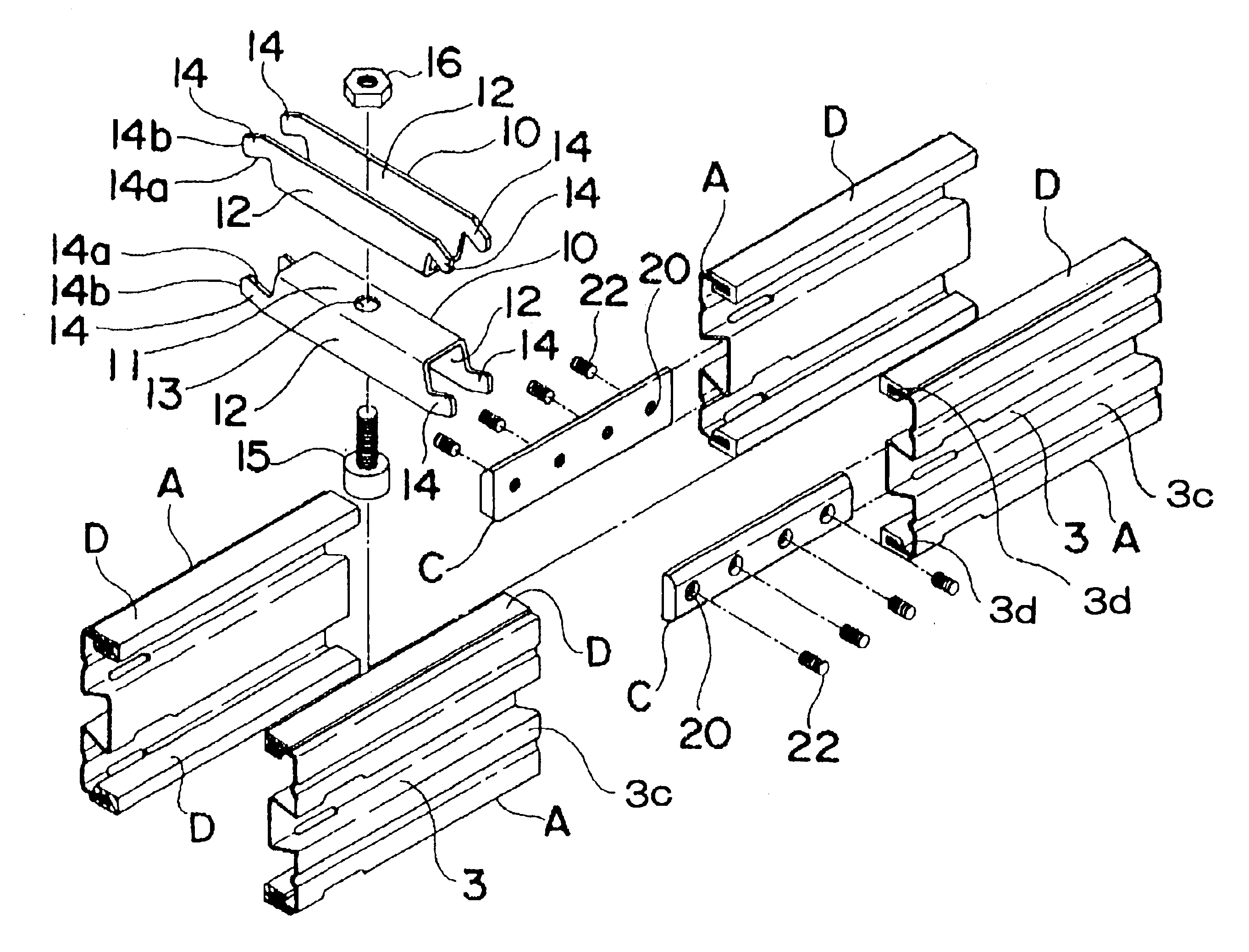
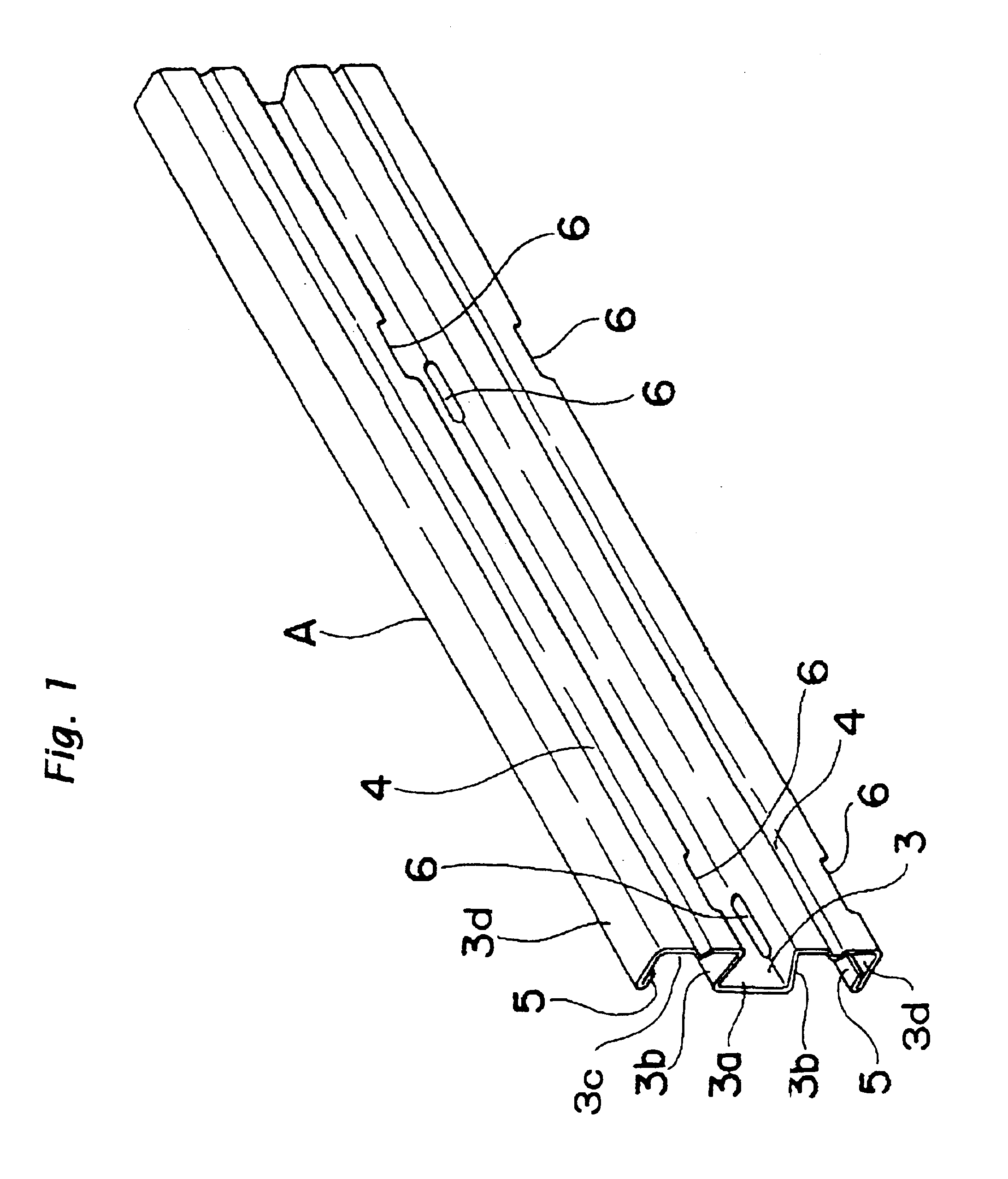
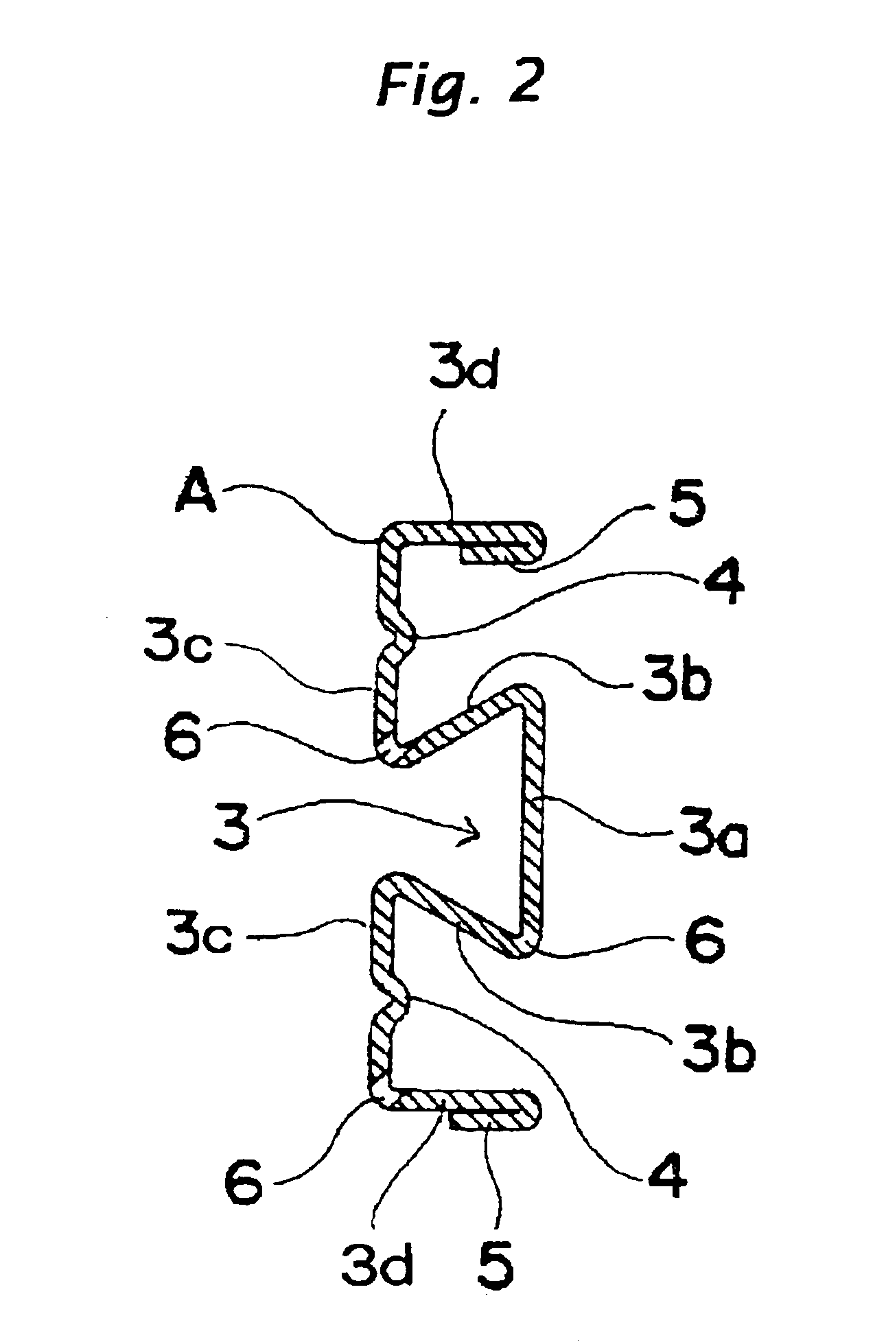
Through the accompanying drawings, the frame member according to the present invention is indicated with a reference A. The frame member A is used as a traveling frame assembly, guide rail, receiving rail or the like used in a conveyor system. It is formed from an elongated rectangular steel plate to have desired dimensions and shape for any intended purpose, for example.

As shown, the frame member A consists of a rear section 3a extending longitudinally of the frame member A and having a predetermined width and a length larger than the width, a pair of inclined sections 3b contiguous to lateral ends of the rear section 3a and extending in converging directions away from the rear section 3a, the rear section 3a and pair of inclined sections 3b defining together a structure having a generally C-like vertical cross section, a pair of front sections 3c contiguous to lateral ends of the inclined sections 3b and extending in directions generally parallel to the rear section 3a, and a pair...


PUM


Abstract

A metallic frame member provided for use in a traveling frame assembly, guide rail or receiving rail in a conveyor system. A rear section extends longitudinally of the frame member. A pair of inclined sections are bent in directions in which they extend towards each other from lateral ends of the rear section. A pair of front sections are bent in directions in which they extend from lateral ends of the pair of inclined sections generally in parallel to the rear section. A pair of side sections are bent from lateral ends of the front sections towards the rear section. The rear section and pair of inclined sections define a longitudinal concavity having a generally C-like vertical cross-sectional profile. Each of the side sections are folded back at the free end inside or outside thereof to form a folded portion.

Description

FIELD OF THE INVENTIONThe present invention relates to a metallic frame member having fitted thereon a plastic traveling rail usable, for example, as a traveling frame assembly, guide rail, receiving rail or the like in the field of conveyor system, and a traveling frame assembly constructed of the frame for use with a conveyor chain or the like.BACKGROUND ARTThe conventional frame member of the above type is formed from iron or stainless steel. The frame member is formed by bending a steel plate of a suitable thickness and proper length by a press or bender to make a simple long structure, and connecting a plurality of such structures to each other, for example.The conventional frame member is also formed by an extrusion molding from aluminum. The frame member of this type is advantageous in that it can easily be formed to have any complicated shape as desired.The traveling rail laid under a conveyor chain is formed by working or extrusion molding, for example. For installing the t...

Claims


Application Information

Patent Timeline
IPC IPC(8): B65G21/00B65G21/02B65G21/20B65G21/22
CPCB65G21/06B65G21/22B65G21/2072
Inventor TERAJIMA, ATUSIKOEDA, MOTOYAFUKAZAWA, SEIICHIKOBAYASHI, KAZUYUKIKATO, FUKUKAZU
Owner TSUBAKI YAMAKYU CHAIN
Why Eureka
Try Eureka