
Universal license plate cord winder

a license plate and cord winder technology, applied in the field of universal license plate cord winders, can solve the problems of inability to stabilize the housing, inability to adapt to the weather, and failure of invention, so as to prevent the connection from being exposed to the weather elements, and increase the usable length

Inactive Publication Date: 2005-02-15
DESORMEAUX DONALD +2
View PDF8 Cites 31 Cited by
  • Summary
  • Abstract
  • Description
  • Claims
  • Application Information

AI Technical Summary

Benefits of technology

In one aspect of the invention, a flat-type cord is used for the extension portion so as to allow a more compact reeling of said cord thereby increasing the usable length.
In another aspect of the invention, the female receptacle is extended from the housing in order to make the connection to the electrical device within the vehicle's engine or rear compartment thereby preventing exposure of the connection to the weather elements.
Accordingly, the system of the present invention therefore provides an unobtrusive, thin, easy to-use electrical cord-winding device universally mountable to any North-American-style license plate bracket while providing for a sheltered connection from the elements.

Problems solved by technology

However, this invention, like most of this nature will fail when attempting to plug a block heater within the housing at the license plate area since most block heater cords are too short to reach much past the front edge of the vehicle's hood.
Furthermore, at a typical diameter of 5.5 inches, which is the standard height of a license plate, can only hold a limited length of standard round extension cord material thereby limiting said cord to an impractical length.
Additionally, there are no means to stabilize the housing when mounted since the unfastened edge would be separable for the license plate mounting bracket.
The application of the device is clearly limited to trailer wires and therefore impractical for bloc heaters.
Again, there are no means to stabilize the housing when mounted since the unfastened edge would be separable for the license plate mounting bracket.

Method used


Image

  • Universal license plate cord winder
  • Universal license plate cord winder
  • Universal license plate cord winder

Examples


Embodiment Construction

In the following description, similar features in the drawings have been given similar reference numerals.

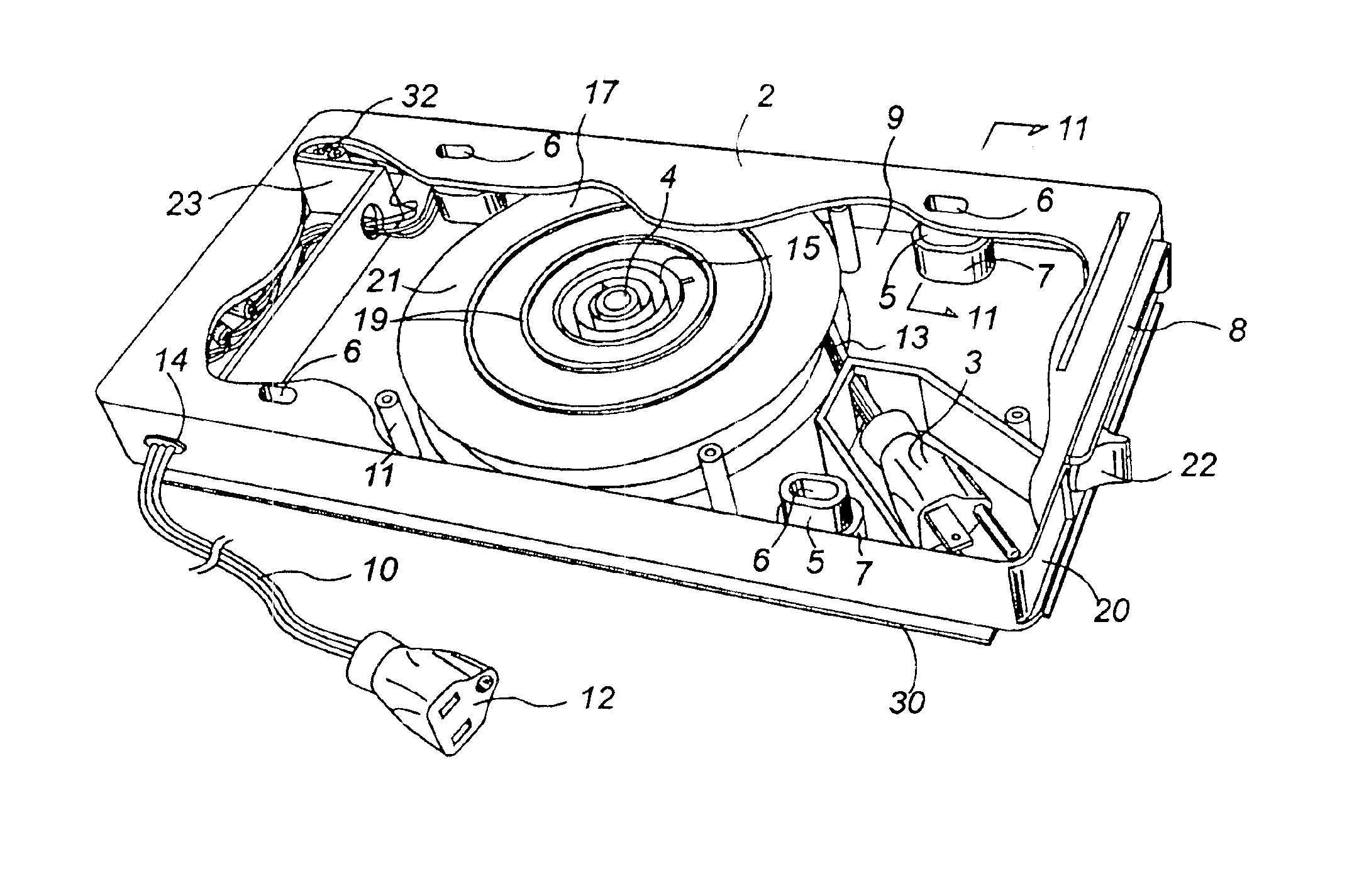
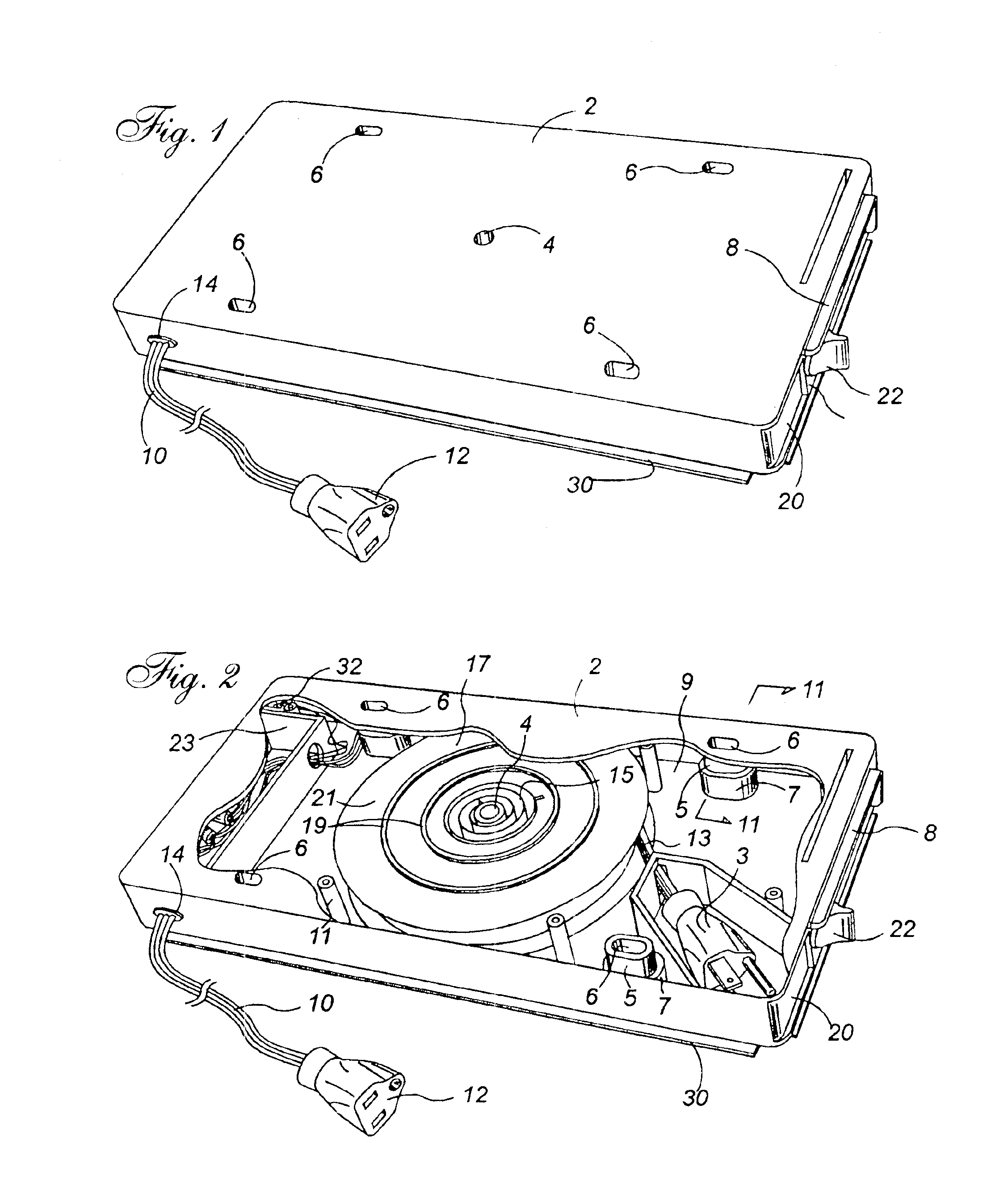
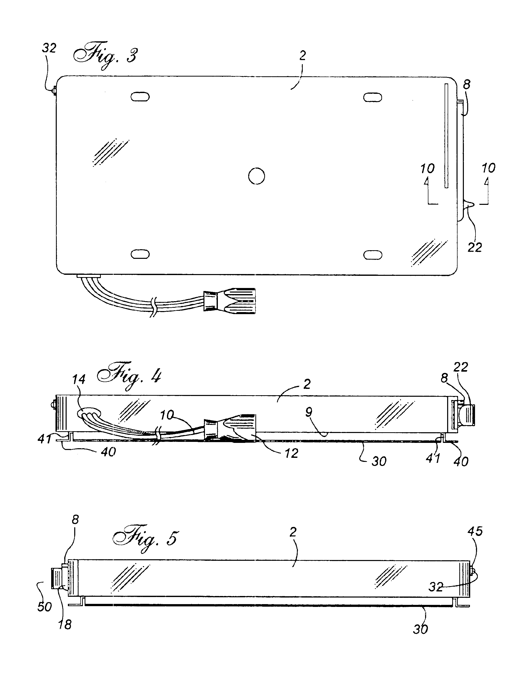
Turning to the drawings, in particular, FIG. 1, which illustrates a perspective view from below of the universal license plate cord winder of the present invention showing; a housing 2 having an inner molded spindle 4, a plurality of mounting bolt holes 6, a splatter guard 8, a receptacle cord 10, a receptacle cord outlet 12 and cord to housing connecting member 14, a hatch assembly having; a hatch 20, and knob 22, and a mounting plate 30.

Turning now to FIG. 2, a cutout perspective view from below of the universal license plate cord winder of the present invention comprising; a housing 2 having an inner molded spindle 4, a plurality of elongated mounting screw holes 6 having hole extensions 5, a plurality of screw assembly receivers 11, a splatter guard 8, a receptacle cord 10, a receptacle cord outlet 12, a cord to housing connecting member 14, and a power-on indicator light 32...


PUM


Abstract

The present invention relates to an improved cord-winding device universally mountable to any front or rear North-American-style license plate bracket, accommodating all electrical devices, which require a 120VAC power supply for a vehicle. The present invention comprises; a housing containing: a reel, a connection box, a male cord housing, a cord hatch and mounting holes, a closure plate and a universal mounting plate. A female receptacle extends from the housing to allow electrical connections to be made in a place away from weather exposure such as engine or rear compartment. The universal license plate cord winder of the present invention can thereby be mounted either from the top or the bottom of housing without compromising the structural integrity of the attachment while maintaining a water tightness required by such a device.

Description

FIELD OF THE INVENTIONThe present invention relates to an improved cord-winding device universally mountable to any front or rear North-American-style license plate bracket, accommodating all electrical devices, which require a 120VAC power supply for a vehicle. The present invention comprises; a housing containing: a reel a connection box, a male cord housing, a cord hatch and mounting holes, a closure plate and a universal mounting plate. A female receptacle extends from the housing to allow electrical connections to be made in a place away from weather exposure such as engine or rear compartment. The universal license plate cord winder of the present invention can also be mounted either from the top or the bottom of housing without compromising the structural integrity of the attachment while maintaining a water tightness required by such a device.BACKGROUND OF THE INVENTIONIt is common for conventional electric or hybrid vehicles to be adapted with components, which require a 12...

Claims


Application Information

Patent Timeline
Patent Type & Authority Patents(United States)
IPC IPC(8): B60R13/10B60R13/00B65H75/42B65H75/38H02G11/02H02G11/00
CPCB60R13/105B65H75/425H02G11/02B60L11/1818B60L11/1824Y02T10/7005Y02T90/121B60L2230/12Y02T10/7094Y02T90/14B60L53/16B60L53/18Y02T10/70Y02T10/7072Y02T90/12
Inventor DESORMEAUX, DONALDDUCHARME, BRUNONANEFF, ALEX
Owner DESORMEAUX DONALD
Learn More