
Electric injection molding machine for controlling injection speed and injection pressure of electric injection molding machine

a technology of injection molding machine and injection pressure, which is applied in the direction of auxillary shaping apparatus, manufacturing tools, food shaping, etc., can solve the problems of unstable resin state, unstable control, and unstable instruction value used for pressure control

Inactive Publication Date: 2005-02-15
MITSUBISHI HEAVY IND LTD
View PDF18 Cites 12 Cited by
  • Summary
  • Abstract
  • Description
  • Claims
  • Application Information

AI Technical Summary

Benefits of technology

Consequently, in the velocity control, the force applied to the resin is detected, and the velocity target value is corrected in response to the detected force and the operation of the electric motor is controlled by the velocity feedback control so that the actual velocity may be equal to the velocity target value. Therefore, the forward movement of the screw can be performed while the force acting upon the screw from the resin is caused to run in in its decreasing direction. Naturally, different from the prior art, changeover between the velocity control and the pressure control is not performed frequently in response to a filling situation of the resin, and stabilized control can be achieved.
Meanwhile, in the pressure control, the detected force and the preset value of the force to be applied to the resin are compared with each other, and the velocity target value is determined in response to a difference between them. Then, the velocity feedback control is performed so that the actual velocity may be equal to the determined velocity target value to control the operation of the electric motor. Consequently, by performing such pressure control as to make the force applied to the resin and the preset value coincide with each other, dwelling can be performed appropriately and the shrinkage by cooling after the resin filling can be corrected appropriately.
Further, where, upon the velocity control, decreasing correction for the velocity target value for the injection screw in response to the force detection value is not performed until the position detection values approaches a value within a predetermined distance to the predetermined position after the velocity control is started, but decreasing correction for the velocity target value for the injection screw is performed in response to the force detection value on condition that the position detection value comes within the predetermined distance to the predetermined position, the advantages that the startup characteristic when the control is started is improved and that a pressure overshoot in the proximity of the changeover position from the velocity control to the pressure control can be prevented are achieved.

Problems solved by technology

However, in the apparatus (shown in FIG. 12) which performs selection between the motor instruction value utilized for the velocity control and the motor instruction value utilized for the pressure control through the low select in such a manner as described above, the apparatus disclosed in the official gazette of Japanese Patent Utility Model Publication No. 28253 / 1994, and the apparatus disclosed in the official gazette of Japanese Patent Publication No. 67722 / 1995, it sometimes occurs that the changeover between the velocity control and the pressure control is performed frequently, and as a result, there is a disadvantage that the control is not stabilized.
In particular, in a situation wherein the control mode is changed over from the velocity control to the pressure, since the viscosity of the filled resin rises and the filled resin solidifies gradually, the state of the resin is very unstable, and therefore, the motor instruction value utilized for the velocity control and the motor instruction value utilized for the pressure control are not stabilized.
Therefore, if the selection between the motor instruction value utilized for the velocity control and the motor instruction value utilized for the pressure control is performed through the low select in such a manner as described above, then the changeover between the velocity control and the pressure control is performed frequently, and as a result, the control is not stabilized.
Consequently, not only the filling of the resin cannot be performed stably but also there is the possibility that some dispersion may occur in the quality of the molded products.
Further, in the technique wherein the changeover between the velocity control and the pressure control is performed in response to the position of the injection screw based on a result of performance by a skilled operator, if the V / P changeover is performed in response to the position of the injection screw set in advance, then the filling of the resin cannot be performed stably, and there is the possibility that dispersion may occur in the quality of the molded products.
In this case, even if the control is stabilized, the control instruction value of the pressure feedback upon transition is not necessarily appropriate, and not only the filling of the resin cannot be performed suitably but also there is the possibility that some dispersion may occur in the quality of the molded products.

Method used


Image

  • Electric injection molding machine for controlling injection speed and injection pressure of electric injection molding machine
  • Electric injection molding machine for controlling injection speed and injection pressure of electric injection molding machine
  • Electric injection molding machine for controlling injection speed and injection pressure of electric injection molding machine

Examples


first embodiment

[1] Description of the First Embodiment

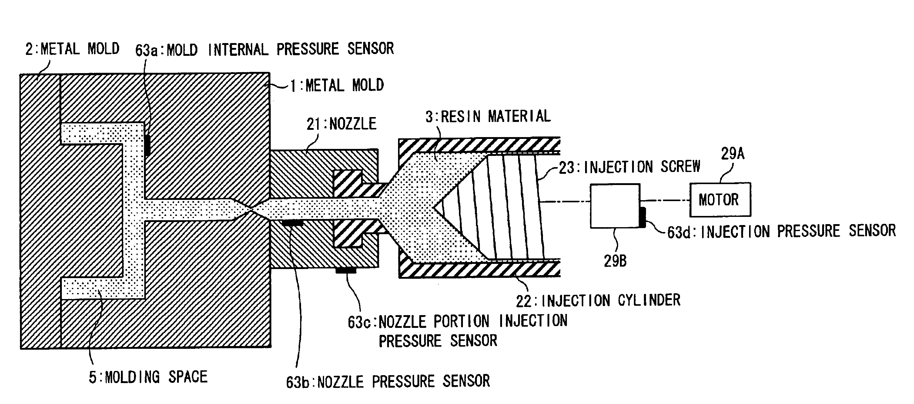
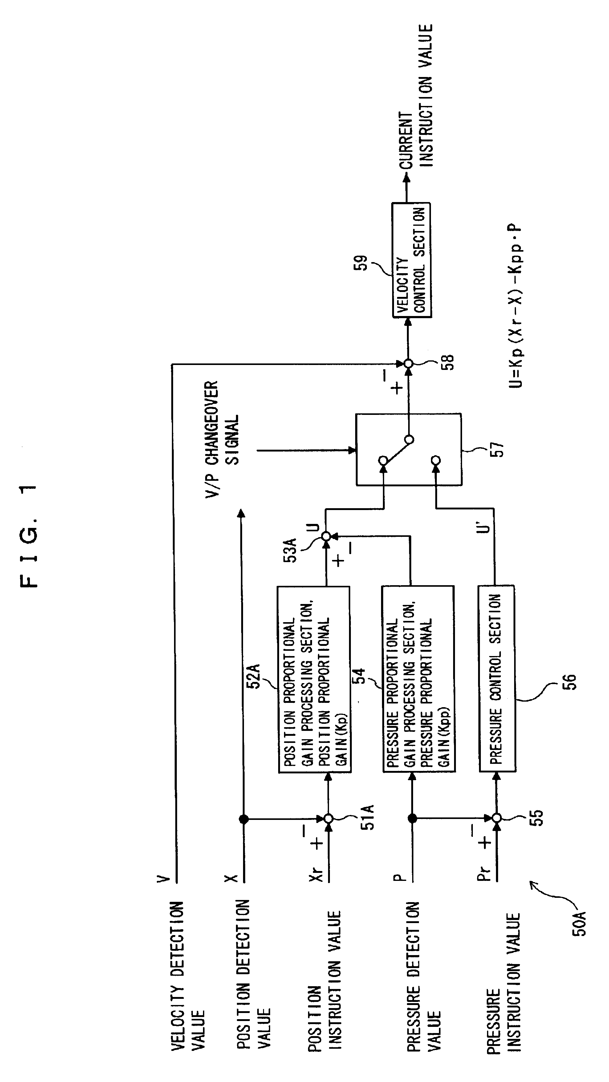
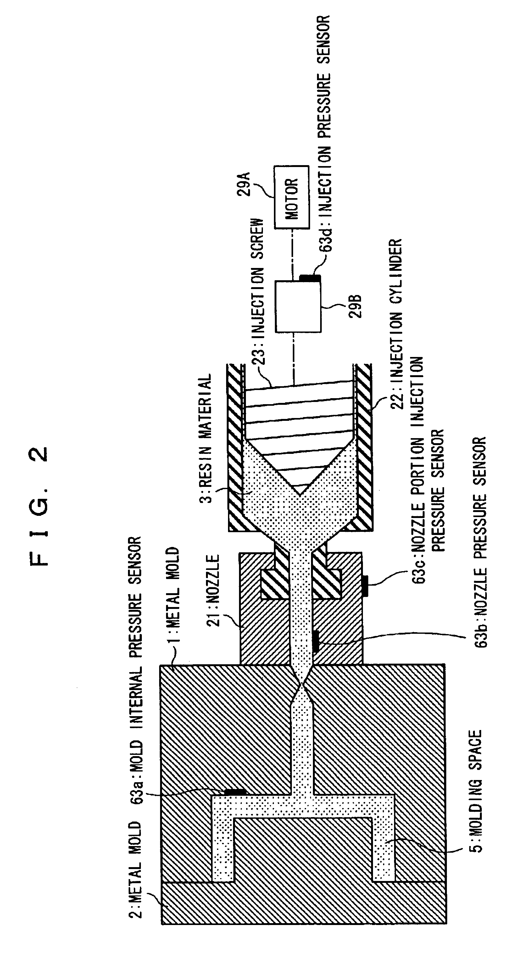
First, an electric injection molder according to a first embodiment of the present invention is described. FIG. 1 is a control block diagram of a forward and backward driving system for an injection screw of the electric injection molder, and FIG. 2 is a schematic sectional view showing a nozzle of the injection screw. It is to be noted that, since the electric injection molder is configured similarly to the prior art shown in FIGS. 9(a) to 9(c) and 10(a) to 10(c) except the back and forth driving system for the injection screw, simplified description of the same is given.

First, a general configuration of the electric injection molder is described. As shown in FIGS. 9(a) to (c) and 10(a) to 10(c), the injection molder shown includes a mold closing apparatus 10 for stacking two metal molds 1 and 2, and an injection apparatus 20 for injecting and supplying raw resin (resin material) 3 into a space formed between the metal molds 1 and 2.

The mold c...

second embodiment

[2] Description of the Second Embodiment

Now, an electric injection molder as a second embodiment of the present invention is described. FIG. 3 is a control block diagram of a forward and backward driving system for an injection screw of the electric injection molder. It is to be noted that, since the present electric injection molder is configured similarly to that of the first embodiment except part of the control apparatus (velocity control system), description thereof is omitted or simplified.

According to the control apparatus 50B of the present embodiment, the velocity control system in the present embodiment uses a velocity instruction value Vr and a velocity detection value V while the velocity control system in the first embodiment uses the position instruction value Xr and the position detection value X.

In particular, the velocity control system in the present embodiment includes an adder 51B for subtracting a velocity detection value V from a velocity instruction value Vr t...

third embodiment

[3] Description of the Third Embodiment

Now, an electric injection molder as a third embodiment of the present invention is described. FIG. 4 is a control block diagram of a forward and backward driving system for an injection screw of the electric injection molder. It is to be noted that, since the present electric injection molder is configured in a similar manner to those of the first and second embodiments except part of a control apparatus (except a velocity control system), description of it is omitted or simplified.

In the control apparatus 50C in the present embodiment, the velocity control system is a combination of that in the first embodiment and that in the second embodiment.

In particular, the velocity control system in the present embodiment includes an adder 51A for subtracting a position detection value X from a position instruction value Xr to calculate a position deviation (=Xr−X), a position proportional gain processing section 52A for multiplying the position deviat...


PUM

PropertyMeasurementUnit
Currentaaaaaaaaaa
Pressureaaaaaaaaaa
Shrinkageaaaaaaaaaa

Abstract

The invention relates to an electric injecting molder and an injection velocity and injection pressure controlling method for an electric injecting molder, and it is an object of the present invention to make it possible, in injection molding by an electric injection molder, to mold stable resin products having a minimized dispersion in the quality even if the operation environment varies. When an injection screw (23) disposed in an injection cylinder (22) is driven to move in forward and backward directions by an electric motor (29A) to inject resin material (3) in the injection cylinder (22) into a metal mold (1, 2) to fill the metal mold (1, 2), the electric motor (29A) is first velocity-controlled to fill the resin material (3) into the metal mold (1, 2), and, after the filling, the electric motor (29A) is pressure-controlled to replenish the resin material for shrinkage of the resin. Upon the velocity control, a velocity target value for the injection screw (23) is corrected in response to a force detection value so that the velocity target value for the injection screw (23) may decrease as the force detection value increases to perform velocity feedback control of the electric motor (29A) so that a velocity detection value from velocity detection means may be equal to the velocity target value.

Description

TECHNICAL FIELDThis invention relates to an electric injection molder and an injection velocity and injection pressure controlling method for an electric injection molder wherein an injection screw is driven to move in back and forth directions by an electric motor and the electric motor is controlled in accordance with two control modes of velocity control and pressure control.BACKGROUND ARTAs shown in FIGS. 9(a) to 9(c) and 10(a) to 10(c), an injection molder stacks two metal molds 1 and 2, and supplies a raw resin (resin material) 3 into a space formed between the metal molds 1 and 2 to mold a resin product having a desired shape. To this end, the injection molder includes a mold closing apparatus 10 for stacking the two metal molds 1 and 2 and an injection apparatus 20 for injecting and supplying the raw resin 3 into the space formed between the metal molds 1 and 2. It is to be noted here that the metal mold 1 is formed in a concave shape, and the metal mold 2 is formed in a con...

Claims


Application Information

Patent Timeline
IPC IPC(8): B29C45/77B29C45/76B29C45/47
CPCB29C45/77B29C2945/76943B29C2945/76006B29C2945/76013B29C2945/76083B29C2945/7611B29C2945/76113B29C2945/76187B29C2945/7621B29C2945/76254B29C2945/76257B29C2945/76404B29C2945/76498B29C2945/76598B29C2945/76665B29C2945/76735B29C2945/76859B29C2945/76882B29C2945/76933B29C2945/76936B29C2045/776
Inventor TSUTSUI, KENJIMAEKAWA, AKIHIROMURATA, TADASHIMURASE, JUNJI
Owner MITSUBISHI HEAVY IND LTD
Learn More