
Laser microscope

a laser microscope and microscope technology, applied in the field of laser microscopes, can solve the problems of multiphoton excitation, difficult to put multiphoton excitation methods to practical use, and require a tremendous light intensity

Inactive Publication Date: 2005-02-15
OLYMPUS CORP
View PDF15 Cites 11 Cited by
  • Summary
  • Abstract
  • Description
  • Claims
  • Application Information

AI Technical Summary

Benefits of technology

An object of the present invention is to provide a multiphoton excitation scanning laser microscope, which allows observation easily under the optimum conditions, in accordance with the optical path length of an optical member selectively arranged on an optical path.
a pre-chirp compensator arranged on the optical path for preventing a pulse width of the pulse laser beam from widening due to a wavelength range of the pulse when the pulse laser beam passes through the optical system,

Problems solved by technology

Generally, in a mercury lamp or a continuous oscillation laser used in a fluorescent microscope, the photon density per unit time is low, leading to requirement of a tremendous light intensity for bringing about a multiphoton excitation phenomenon.
Further, it is difficult to put the multiphoton excitation method to practical use unless the problem that a damage done to the optical system or to the sample is increased is solved.
If the difficulty is dealt with by the adjustment of a pre-chirp compensator, another problem is generated that the fluorescent light generated from the sample is faded in proportion to the time spent for the adjustment.
What should be noted is that it is difficult to move the sample back exactly to the original position.
It follows that this method is not practical for the observation and measurement.

Method used


Image

  • Laser microscope
  • Laser microscope
  • Laser microscope

Examples


Embodiment Construction

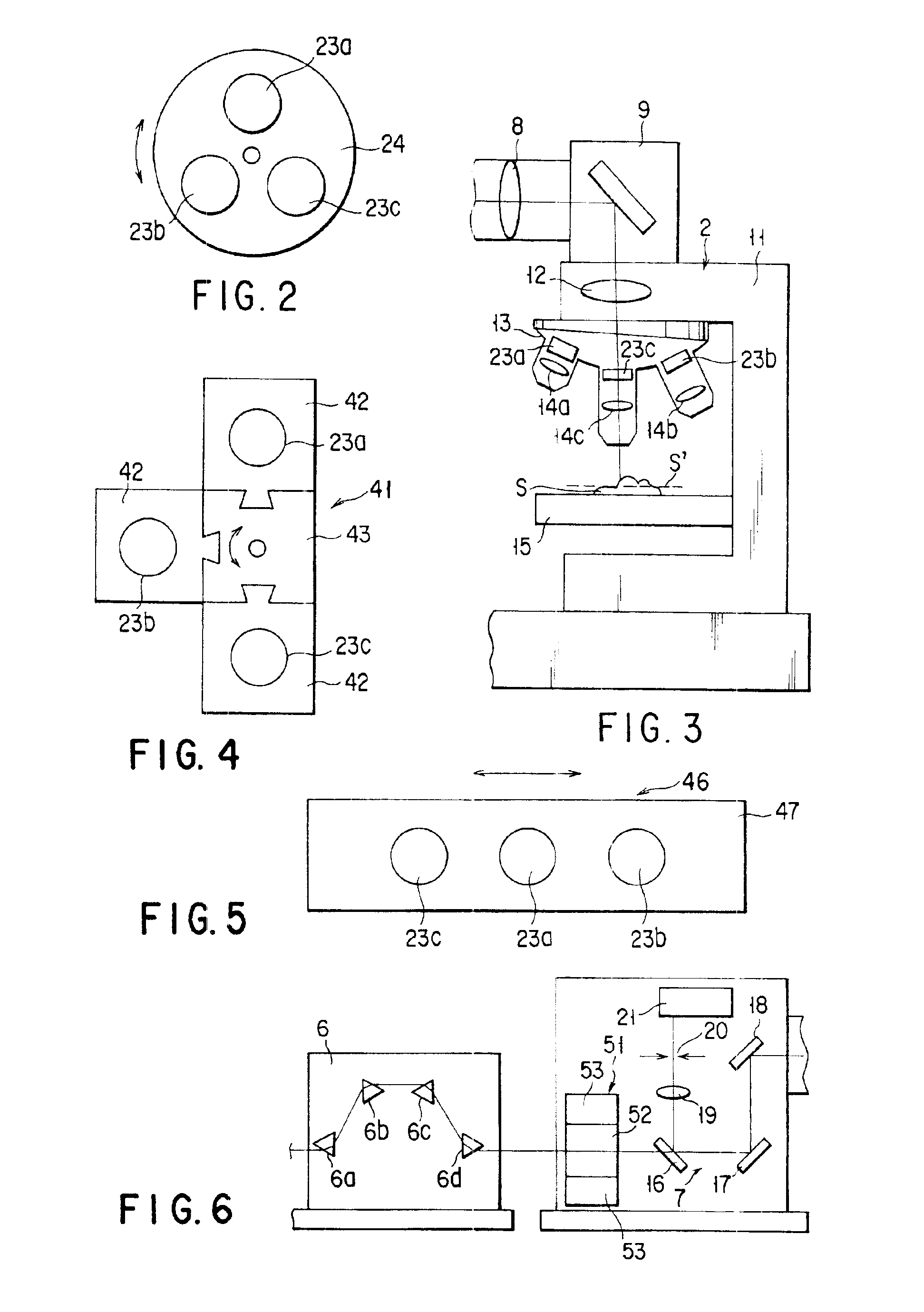
Embodiments of the present invention will be described hereinafter with reference to the accompanying drawing. In the following description, the constituent elements having substantially the same function and arrangement are denoted by the same reference numerals, and a repetitive description will be made only when necessary.

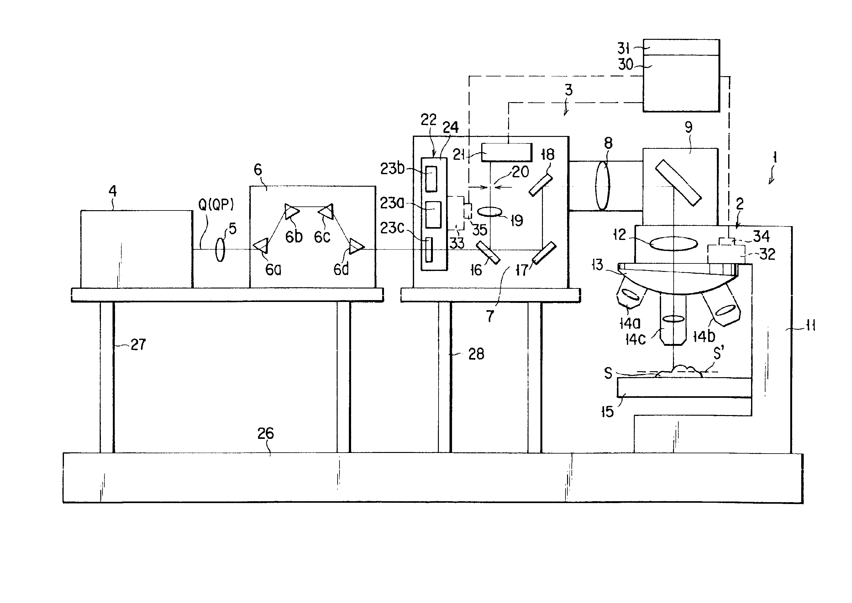
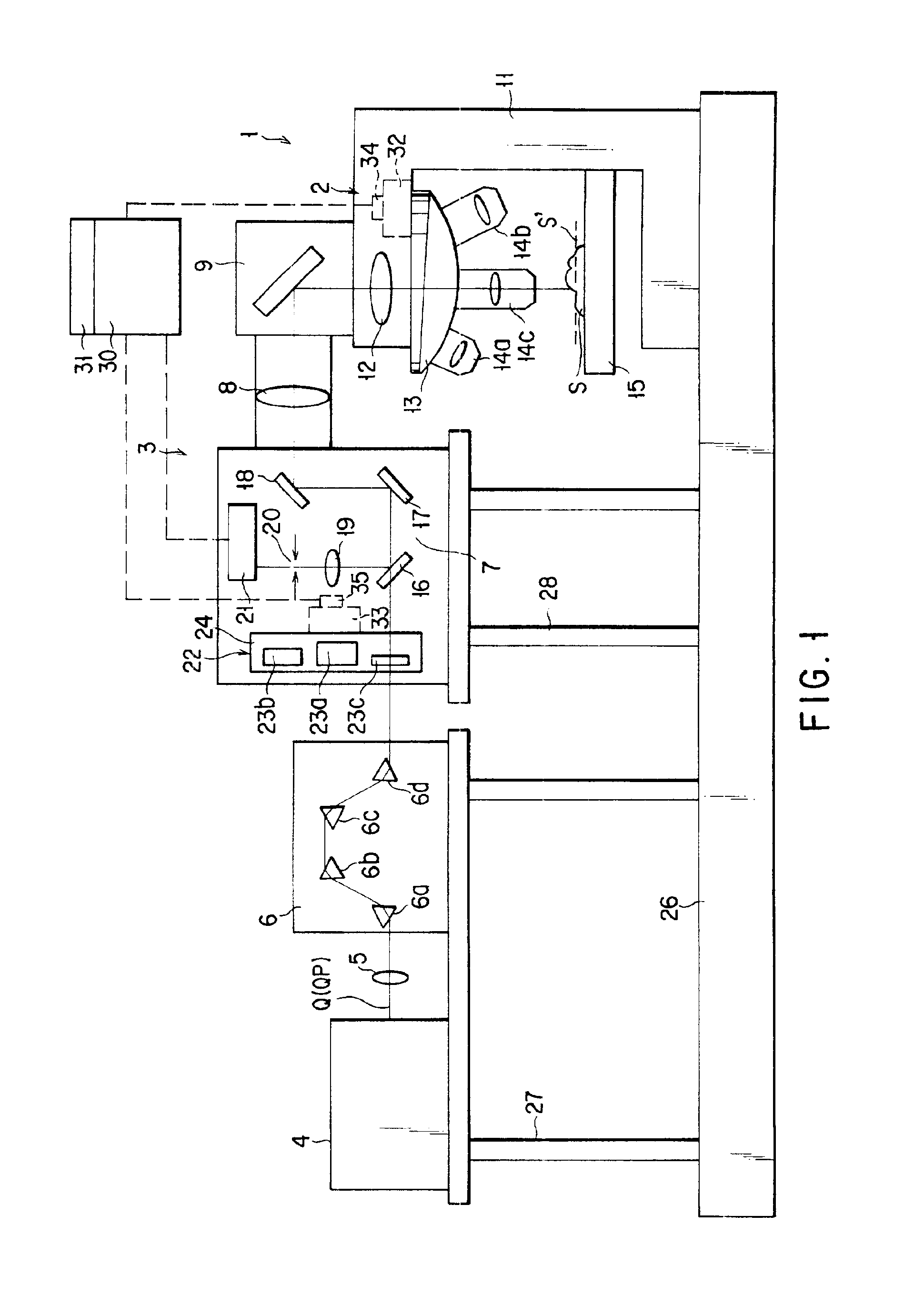
Specifically, FIG. 1 shows the construction of a multiphoton excitation scanning laser microscope 1 according to one embodiment of the present invention.

The microscope 1 comprises a laser beam source 4 for emitting a pulse laser beam for irradiating a sample S, and an optical system 3 forming an optical path for guiding the laser beam from the laser beam source 4 to the sample S. The optical system 3 is formed of a large number of optical elements including the optical elements within a microscope body 2 having a stage 15 on which the sample S is disposed.

The microscope 1 is arranged on a vibration eliminating base 26 for eliminating the vibration transmitted fr...


PUM


Abstract

A multiphoton excitation scanning laser microscope employs a laser beam source for oscillating a pulse laser beam having a wavelength range. A multiphoton excitation phenomenon takes place in a sample irradiated with the laser beam so as to emit a fluorescent light. An optical system for forming an optical path of the laser beam includes a pre-chirp compensator, a scanning optical unit and a plurality of objective lenses differing from each other in magnification and capable of being selectively arranged on the optical path. The optical system also includes a correcting mechanism for causing the pulse width of the laser beam to be constant on a cross section of the sample in the case of selecting any of the objective lenses. The correcting mechanism includes a plurality of correcting plates capable of being selectively arranged on the optical path.

Description

BACKGROUND OF THE INVENTIONThe present invention relates to a laser microscope of the type that a target sample to be observed is irradiated with a pulse laser beam, particularly, to a multiphoton excitation scanning laser microscope for detecting the chemical reaction and fluorescent light caused by the multiphoton absorption of the sample.In the multiphoton excitation method, the excitation which is performed in general by a single photon, is carried out by multiphoton. In, for example, a two-photon excitation method, the fluorescent light excitation, which is performed under a wavelength of 400 nm in the case of using a single photon, is carried out under a wavelength of 800 nm which is two times as long as the wavelength for the case of using a single photon.Generally, in a mercury lamp or a continuous oscillation laser used in a fluorescent microscope, the photon density per unit time is low, leading to requirement of a tremendous light intensity for bringing about a multiphoto...

Claims


Application Information

Patent Timeline
IPC IPC(8): G01N21/64G02B21/16G02B21/24
CPCG01N21/6458G02B21/248G02B21/16
Inventor TOMIOKA, MASAHARU
Owner OLYMPUS CORP
Learn More