Method and apparatus for subterranean formation flow imaging

a technology of flow imaging and subterranean formations, applied in the direction of reradiation, measurement using nmr, instruments, etc., can solve the problems of difficult recognition of pay zones within earth formations, difficult to produce oil or gas, and the effect of borehole rugosity and mudcake on resistivity measuremen

Inactive Publication Date: 2005-02-15
SHELL OIL CO
View PDF106 Cites 136 Cited by
  • Summary
  • Abstract
  • Description
  • Claims
  • Application Information

AI Technical Summary

Benefits of technology

In one embodiment, the present invention utilizes one or more small NMR imaging sensors in conjunction with a formation test tool, the sensors being in or proximate to the borehole wall during the formation test procedures. The present invention is thus capable of performing fluid typing of the fluid in situ as it flows toward the formation test tool probe. This permits a determination of actual flow velocity of connate fluids within the formation based on the displacement of the hydrogen atoms within the formation. It is, thus, further an objective of the present invention to provide for a more accurate determination of permeability, including, anisotropic permeability measured in situ.
The present invention thus provides the user the ability to accurately determine formation parameters as well as obtain a 3-D image of the formation past the borehole wall. This image information can be used in conjunction with other logging information to provide the user with the information required to make decisions regarding the completion and production of wells.

Problems solved by technology

Obviously, if the formation's pore space is completely filled with water, such a formation will not produce oil or gas and is of no interest.
The LWD method, while being more susceptible to environmental effects, such as tool position within the borehole, makes the measurements in a relatively new borehole, generally prior to any invasion by components of the drilling fluids into the formation.
While a number of models have been developed to estimate the water saturation of the formation, the recognition of pay zones within an earth formation is difficult because no conductivity contrast exists between capillary-bound water and moveable water.
Further, the resistivity measurement is subject to borehole rugosity and mudcake effects.
Similarly, the methods utilized to determine porosity were lacking in detail in that neutron-density measurements responded to all components within the formation but are more sensitive to the formation matrix as opposed to the fluids contained therein.
Even after cross plot corrections, borehole rugosity, mudcake, lithology and other environmental effects can adversely effect this measurement.
Each of the above models has drawbacks in their application.
It will be appreciated that models designed to work in a consistent lithology will not yield as accurate a result where the formation is thinly laminated with the layers each having differing porosity and permeability characteristics.
Formation test tools are generally incapable of measuring anisotropic permeability, i.e., vertical versus horizontal permeability.
An additional downside to using formation test tools is the fact that logging tool movement must be stopped to permit the formation test tool to come into contact with formation, perform the draw down and permit the pressure to build back up.
This results in an associated cost over and beyond the cost of services associated with logging.
Thus, while providing some information regarding permeability, formation test tools are costly to use when compared to NMR logging tools.
At the same time, NMR logging tools make certain assumptions regarding permeability that may not be accurate in light of actual formation conditions.
Both of these techniques have their drawbacks in that both require a great amount of time to hold the tools stationary in the borehole in order to make measurements.
Further, commonly used oil-based drilling muds have an adverse effect on the use of the microresistivity method.

Method used


Image

  • Method and apparatus for subterranean formation flow imaging
  • Method and apparatus for subterranean formation flow imaging
  • Method and apparatus for subterranean formation flow imaging

Examples


Embodiment Construction

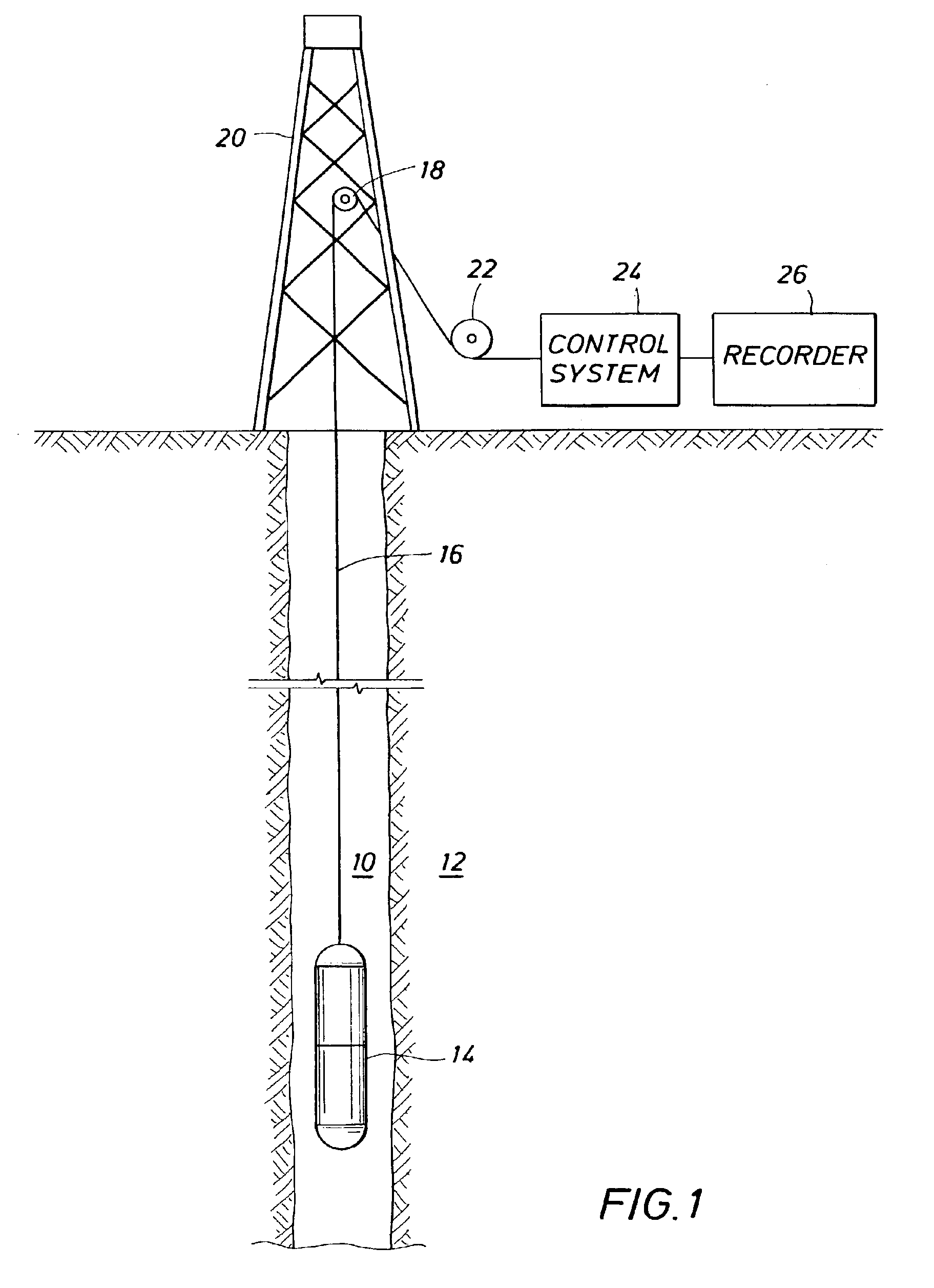
The present invention is intended to be used as an NMR imaging device within a well borehole. Use of the present invention within the well borehole is intended to provide certain formation characteristics, including, porosity, permeability, fluid characterization, flow velocity and 3-D imaging of the formation of interest. With reference to FIG. 1, a well logging system is generally depicted. A well borehole 10 is seen as penetrating earth formation 12, having been drilled using known methods. A well logging tool 14 is seen as being lowered into the well borehole and on an armored, multiconductor cable 16. The tool 14 includes the sensors required for the measurement(s) to be made, power conditioning circuitry, tool control processors, and telemetry circuitry to transmit the information back up the cable 16. The cable 16 is lowered over shiv wheel 18, which is in turn supported by rig 20. The cable 16 is played out from a winch 22, controlled by an operator within a well logging tru...


PUM


Abstract

The present invention relates to a method and apparatus for measuring a property relating to fluid flow in an earth formation, more specifically to directly measuring formation permeability and other fluid characteristics. The present invention provides a method for determining the permeability of a hydrocarbon bearing earth formation, which method comprises the steps of: locating a tool at a selected position in a borehole penetrating the earth formation; inducing a flow of fluid within the earth formation to said tool; creating at least two MRI images of said fluid while flowing within the earth formation to said tool, said at least two images being created at different times; determining displacement of said fluid within the earth formation between said different times, using the at least two MRI images.

Description

FIELD OF THE INVENTIONThe present invention relates to an apparatus and techniques for determining characteristics of Earth formations surrounding a borehole and, more particularly, to an apparatus and method for nuclear magnetic resonance (NMR) borehole logging further being capable of magnetic resonance imaging (MRI) the formations surrounding the borehole and determine other formation characteristics such as porosity and permeability, as well as the characterization of fluids in the formation.BACKGROUND OF THE INVENTIONA major goal in the evaluation of hydrocarbon bearing Earth formations is the accurate determination of the volumes of oil and water in the pore space of sedimentary rocks. Measurements made with signals from logging instruments have been used to obtain estimates of these volumes. The most credible measurement of producibility of the fluid volumes is to actually produce fluids from the formation; such as by using a drill stem test or by using a logging device that ...

Claims


Application Information

Patent Timeline
Patent Type & Authority Patents(United States)
IPC IPC(8): G01V3/32G01R33/44G01V3/18
CPCG01V3/32G01N24/081
Inventor APPEL, MATTHIASFREEMAN, JOHN JUSTINWINKLER, MARIOBLUMICH, BERNHARD PETER JAKOB
Owner SHELL OIL CO
Why Eureka
Try Eureka