

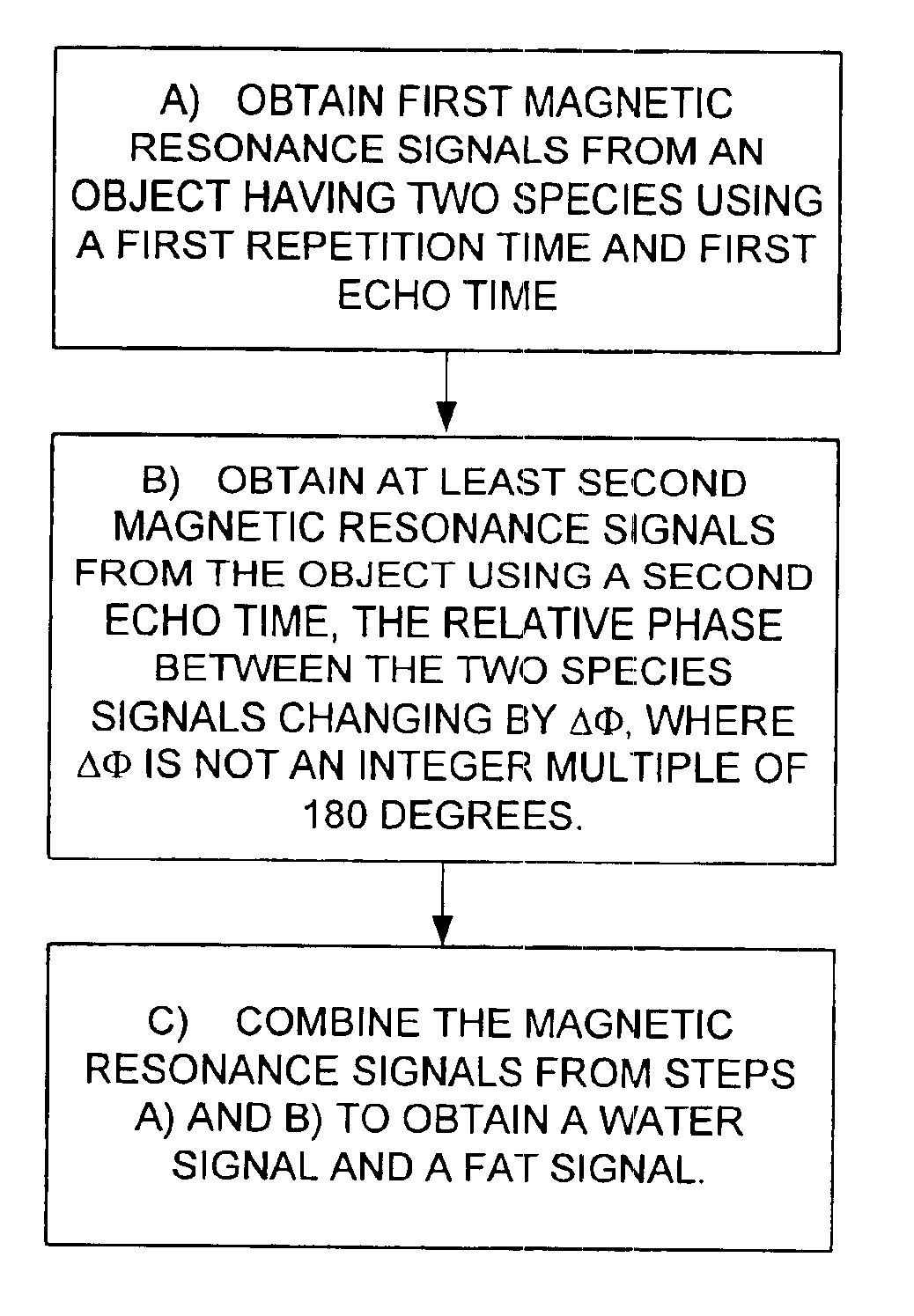
Magnetic resonance imaging with fat-water signal separation
a magnetic resonance imaging and signal separation technology, applied in the field of magnetic resonance imaging (mri), can solve the problem of severe image degradation limitation of ssfp, and achieve the effect of rapid imaging of articular cartilag
- Summary
- Abstract
- Description
- Claims
- Application Information
AI Technical Summary
Benefits of technology
Problems solved by technology
Method used
Image

Examples
Embodiment Construction
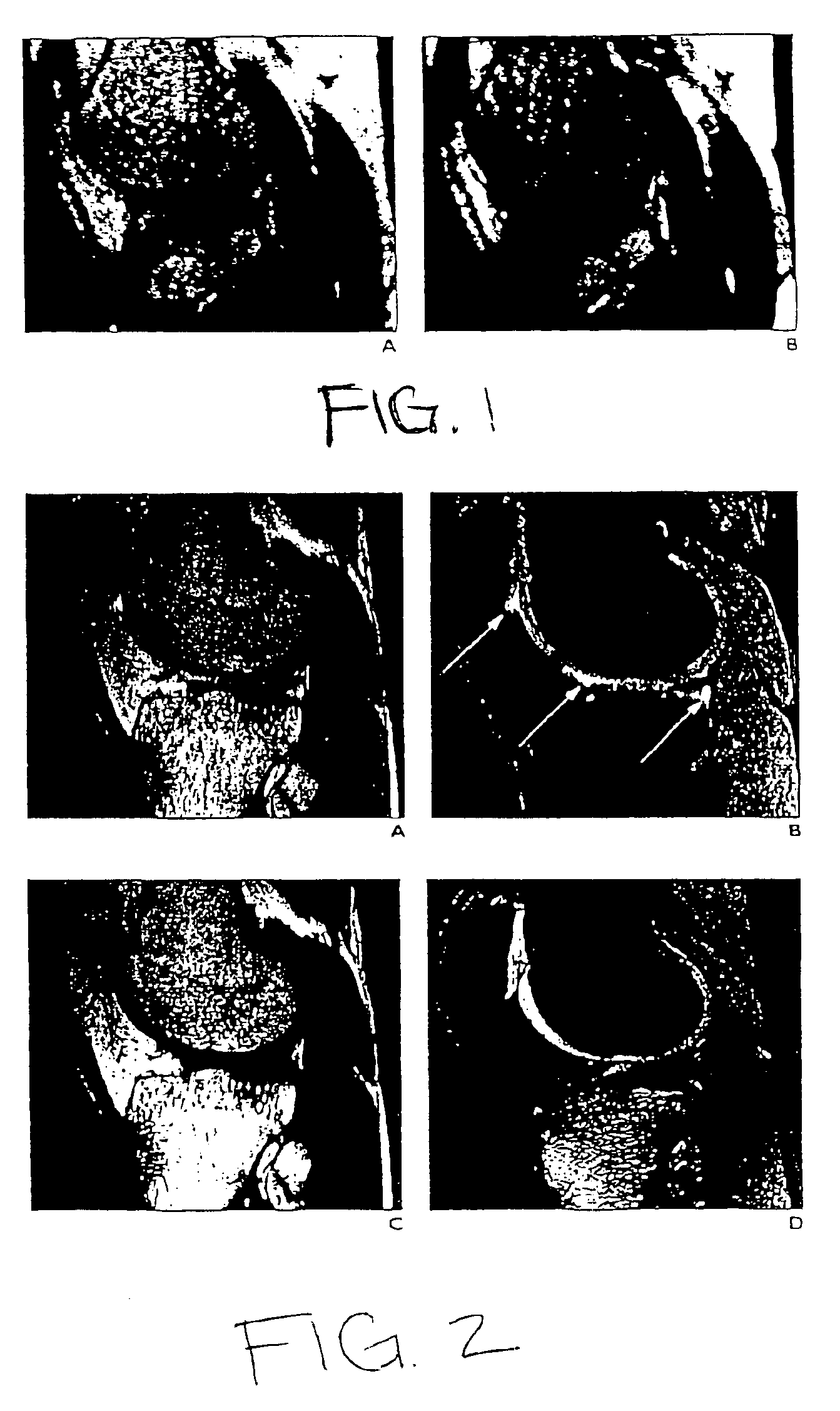
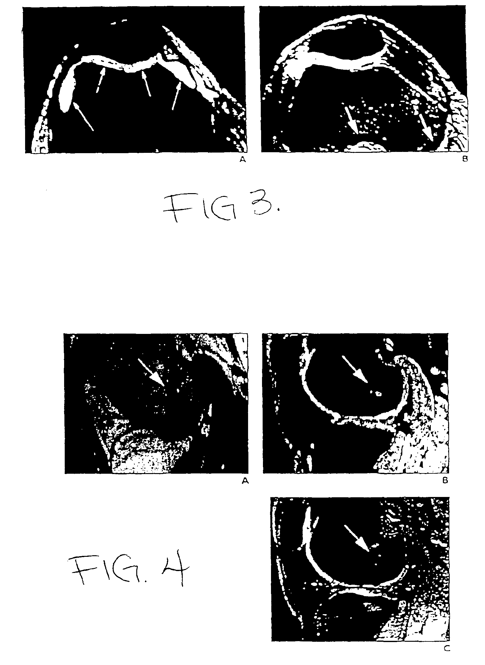
The invention will be described with reference to a generalized mathematical formulation for multi-echo fat-water separation that allows the use of small increments in echo time (TE) in three dimensional (3D) SSFP imaging of articular cartilage in the knees of normal volunteers. Three dimensional spoiled gradient echo images with fat-saturation are shown for comparison.
SSFP and Fat-Water Separation
Separation of fat and water through “in-phase” and “out-of-phase” imaging is an effective approach first demonstrated by Dixon, “Simple Proton Spectroscopic Imaging,” Radiology 1984; 153: 189-194, and further refined by Glover, “Multipoint Dixon Technique for Water and Fat Proton and Susceptability Imaging,” Journal of Magnetic Resonance Imaging 1991; 1:521-530, to compensate for the effects of magnetic field inhomogeneities. Typical three-point sampling schemes acquire spin-echo or gradient echo images with echo time (TE) increments of 0, 2.27, and 4.45 ms, and produce phase increments of...
PUM
 Abstract
Description
Claims
Application Information