Current detecting circuit AC/DC flyback switching power supply

a technology current detecting circuit, which is applied in the direction of power supply testing, process and machine control, instruments, etc., can solve the problems of ac/dc flyback switching power supply efficiency drop, and achieve the effect of reducing the power loss of ac/dc flyback switching power supply tremendously

Inactive Publication Date: 2005-02-15
NIKO SEMICON
View PDF3 Cites 51 Cited by
  • Summary
  • Abstract
  • Description
  • Claims
  • Application Information

AI Technical Summary

Benefits of technology

A main objective of the present invention is to provide a current detecting circuit that can reduce the power loss of the AC / DC flyback switching power supply tremendously.
For reaching the objective above, the present invention provides a current detecting circuit for AC / DC flyback switching power supply. The current detecting circuit is disposed on the secondary side of the transformer for detecting the current alternation of the transformer and timely turning off the FET of the secondary side to prevent the current from flowing backward to the transformer.
The current detecting circuit includes a first transistor and second transistor, i.e. bipolar junction transistors. The first transistor has a base connecting with the base collector of the second transistor to form a common base terminal. The first-transistor has an emitter forming a first detecting terminal and has a collector forming a feedback terminal. The second transistor has an emitter forming a second detecting terminal. The current detecting circuit further includes a field-effect transistor (FET). The FET has a source, a gate and a drain. The source connects to the first output terminal of the transformer. The drain connects to the DC output terminal. Therein, the first detecting terminal is connected with the source of the FET, the second detecting terminal is connected with the drain of the FET and the feedback terminal is connected with the gate of the FET. The FET is turned on by using an auxiliary voltage provided by the transformer via a buffer circuit. Further, by using the bipolar junction transistors to detect the current flowing through the FET, the FET can be turned off while the current approaches zero. Hence, the FET can replace the diode D1 of the conventional AC / DC flyback switching power supply and increase the efficiency.

Problems solved by technology

If the output current is huge, the efficiency of the conventional AC / DC flyback switching power supply will drop substantially.

Method used


Image

  • Current detecting circuit AC/DC flyback switching power supply
  • Current detecting circuit AC/DC flyback switching power supply
  • Current detecting circuit AC/DC flyback switching power supply

Examples


Embodiment Construction

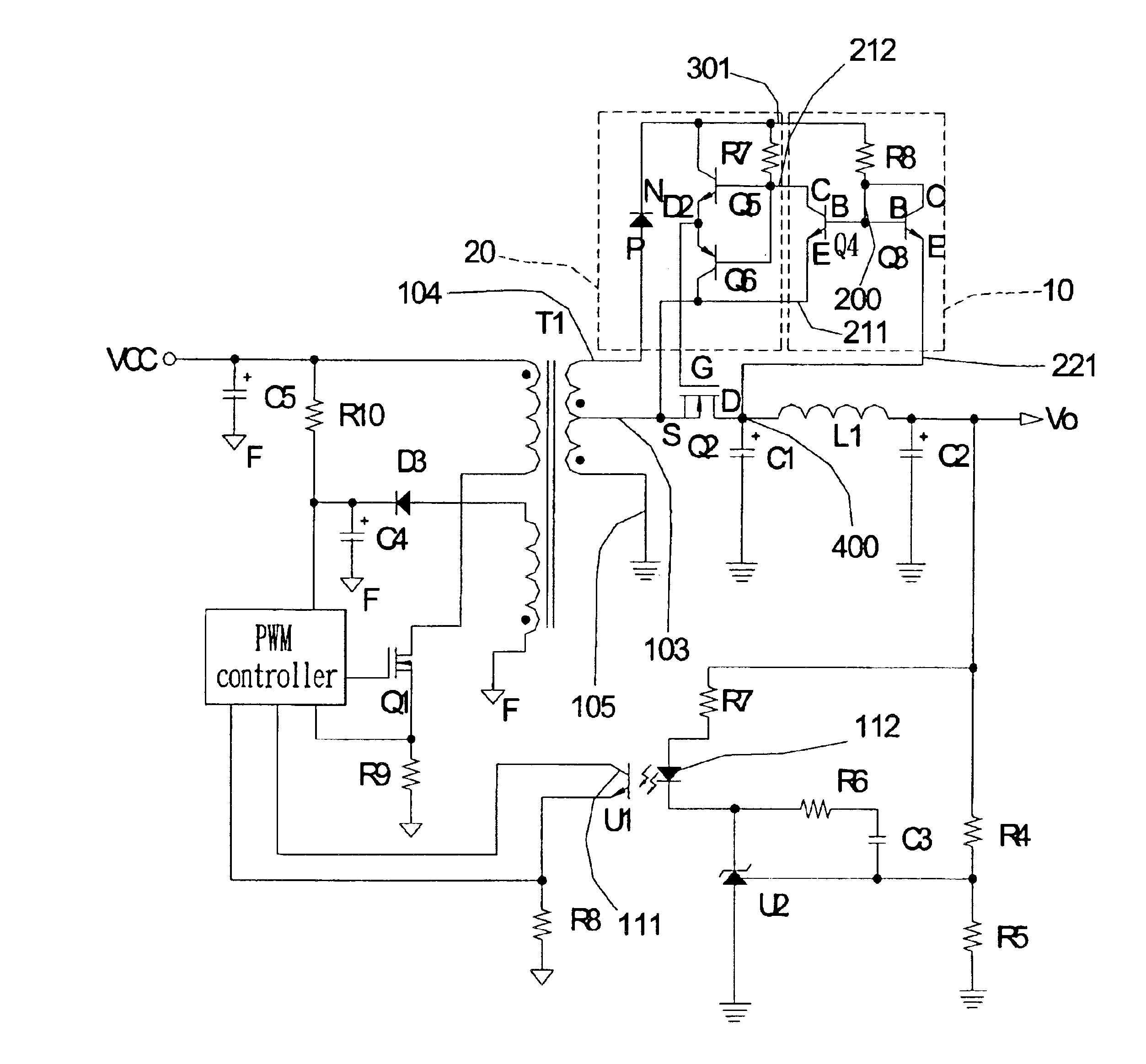
Please refer to FIG. 3, which is a circuit diagram of the present invention. The current detecting circuit 10 of the present invention is connected with an output circuit of a DC power supply for detecting the current outputted from the first output terminal 103 of the transformer T1. While the current decreases and approaches to zero, the current detecting circuit 10 will turn off the FET Q2 timely to prevent the current from flowing backward to the transformer T1 as the FET Q1 is turned on again. While the FET Q1 is turned off, the current detecting circuit 10 will drive the FET Q2 to release the electrical energy stored in the transformer T1. The secondary side of the transformer T1 includes the first output terminal 103, the second output terminal 104 and a reference terminal 105. The reference terminal 105 can be an electrical connection terminal.

The current detecting circuit 10 includes bipolar junction transistors and a first resistor R8. The bipolar junction transistors incl...


PUM


Abstract

A current detecting circuit connects to a secondary side of a transformer, including a first, second transistors and a field-effect transistor (FET). The first transistor has a base connecting with the base and collector of the second transistor to form a common base terminal, an emitter forming a first detecting terminal and an emitter forming a feedback terminal. The second transistor has a collector forming a second detecting terminal. The FET is used to replace a prior current rectifying diode. The FET has a source connecting to an output terminal of the transformer and a drain connecting to a direct current (DC) output terminal. The first, second detecting terminals and feedback terminal are connected with the source, drain and gate of the FET, respectively. Via detecting the current of the DC output terminal, the FET is timely turned on and off to release the energy stored in the transformer.

Description

FIELD OF THE INVENTIONThe present invention is directed to a current detecting circuit for AC / DC flyback switching power supply, and more particularly, to a current detecting circuit disposed on the secondary side of the alternating current / direct current (AC / DC) flyback switching power supply that uses bipolar transistors to detect the current alternation of a transformer and drives a field-effect transistor (FET) to release the stored energy of the transformer timely.BACKGROUND OF THE INVENTIONIn accordance with prior art, a DC power supply, e.g. AC / DC switching power supply, usually employs a high frequency pulse width modulation (PWM) control circuit to control the output voltage for reducing the entire volume. As shown in FIG. 1, which is a schematic diagram of a conventional AC / DC flyback switching power supply. The transformer T1 of the conventional AC / DC flyback switching power supply has two sides that are designated as primary side 101 and secondary side 102, respectively....

Claims


Application Information

Patent Timeline
Patent Type & Authority Patents(United States)
IPC IPC(8): G01R19/00G01R31/40
CPCG01R19/0092G01R31/40
Inventor YANG, HUI CHIANG
Owner NIKO SEMICON
Why Eureka
Try Eureka