

Coaxial type impedance matching device
a technology of impedance matching and coaxial type, which is applied in the direction of waveguide type devices, coupling device connections, resonant antennas, etc., can solve the problems of electromagnetic waves that may leak from a slit formed in the external conductor, the position adjustment of the slugs is seriously complicated, and the cost rise, so as to reduce the leakage of electromagnetic waves
- Summary
- Abstract
- Description
- Claims
- Application Information
AI Technical Summary
Benefits of technology
Problems solved by technology
Method used
Image

Examples
first embodiment
A preferred embodiment of a coaxial type impedance matching device according to the invention will be described with reference to the accompanying drawings.
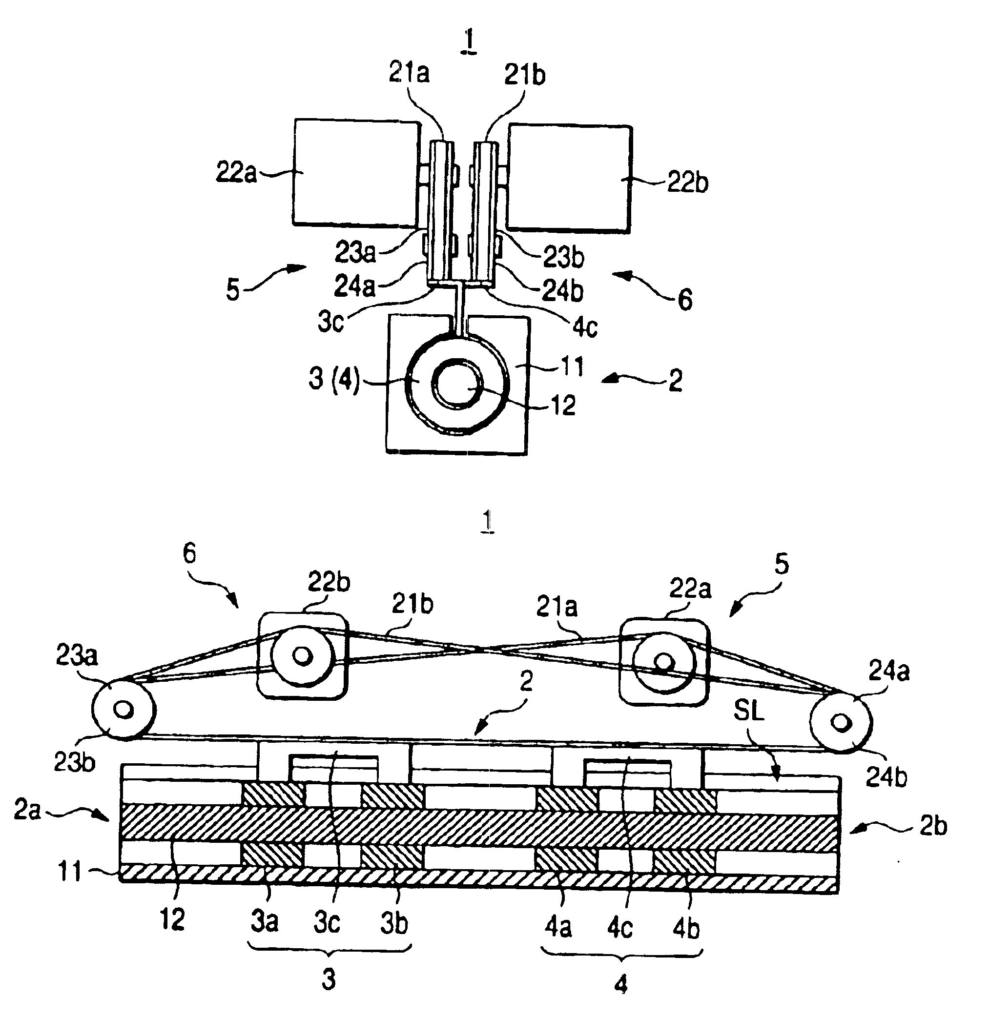
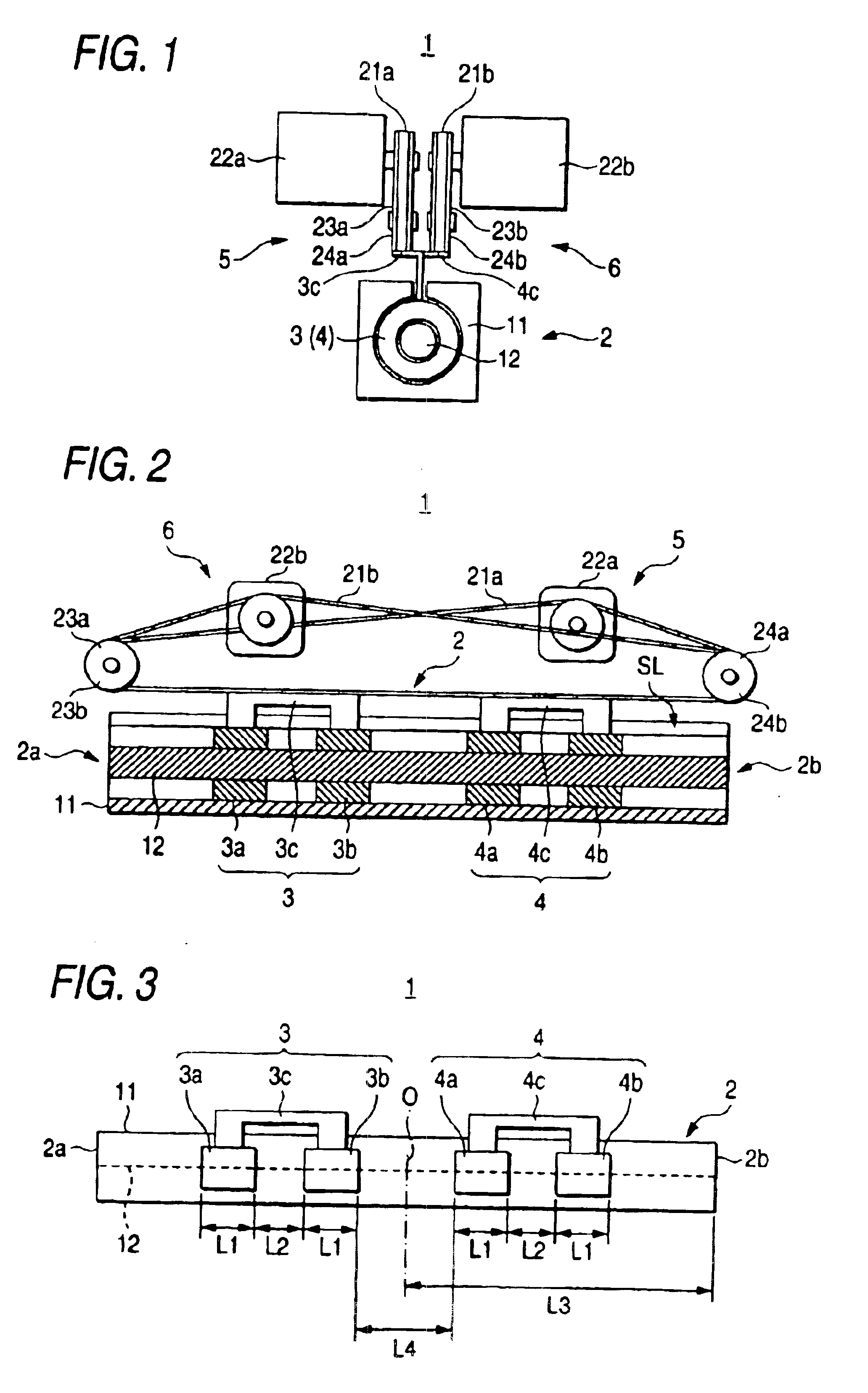
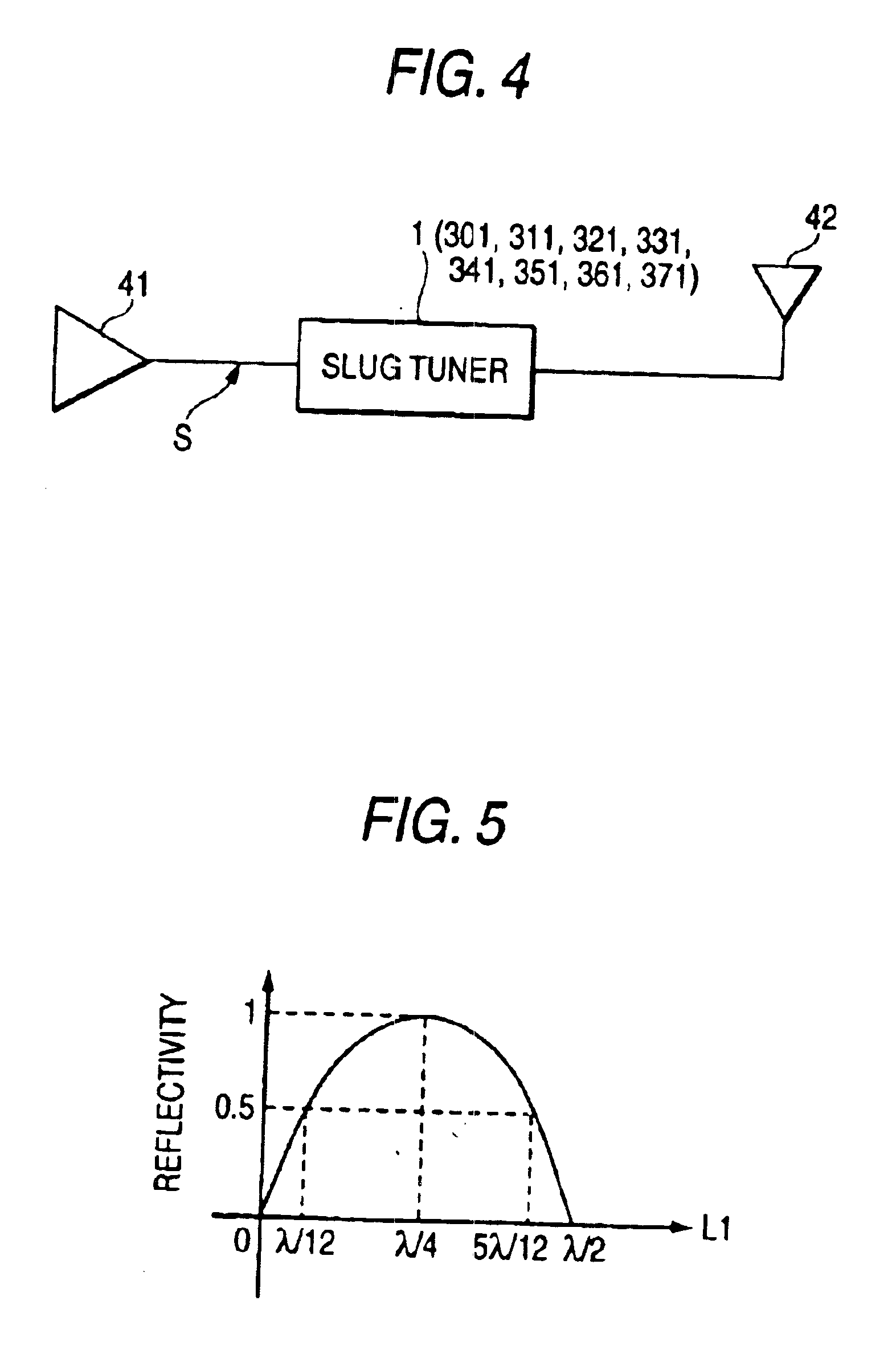
A slug tuner 1, as shown in FIGS. 1 and 2, is an example of the coaxial type impedance matching device according to the invention and is provided with a matching device body 2, an input side slug 3, an output side slug 4 and moving mechanisms 5 and 6. This slug tuner 1 is arranged, for example, between an amplifier 41 and an antenna 42, as shown in FIG. 4. By matching the impedances between the amplifier 41 and the antenna 42, a signal S (as exemplified to have a frequency of 2.45 GHz) outputted from the amplifier 41 is substantially completely outputted with little reflection to the antenna 42. As shown in FIGS. 1 and 2, the matching device body 2 is provided with an external conductor 11 of a square-cylinder shape (or tubular shape) having a circular bore formed longitudinally of its center, and a bar-shaped internal conductor ...
second embodiment
A slug tuner 201, as shown in FIGS. 6 to 8, is an example of the coaxial type impedance matching device according to a second embodiment of the invention and is constructed to include a matching device body 202, an input side slug 203, an output side slug 204 and connector units 205 and 206. This slug tuner 201 is arranged, for example, between an amplifier 241 and an antenna 242, as shown in FIG. 63. By matching the impedances between the amplifier 241 and the antenna 242, a signal S (as exemplified to have a frequency of 2.45 GHz) outputted from the amplifier 241 is substantially completely outputted with little reflection to the antenna 242. As shown in FIGS. 6 and 7, the matching device body 202 is provided with an external conductor 211 of a square-cylinder shape (or tubular shape) having a circular bore formed longitudinally of its center, and a bar-shaped internal conductor 212 housed in the circular bore of the external conductor 211. In this case, as shown in FIG. 6, at the...
third embodiment
A slug tuner 301, as shown in FIGS. 13 and 14, is an example of the coaxial type impedance matching device according to the third embodiment of the invention and is provided with an external conductor 302, an internal conductor 303, dielectrics (slugs) 304 and 305, and a shielding mechanism 306.
The external conductor 302 is formed, for example, into a tubular shape (or a circular-cylinder shape) having a circular bore formed in the longitudinal direction at its central portion. In the external conductor 302, moreover, one slit SL is formed in the longitudinal direction (or in parallel with axis) for providing the communication between the outside and the inside of the external conductor 302.
The internal conductor 303 is formed into a round bar shape (or a circular-cylinder shape) and is so housed in the circular bore of the external conductor 302 that their axes may be aligned with each other (or coaxially). In this case, the internal conductor 303 constructs a signal transmission l...
PUM
 Abstract
Description
Claims
Application Information