

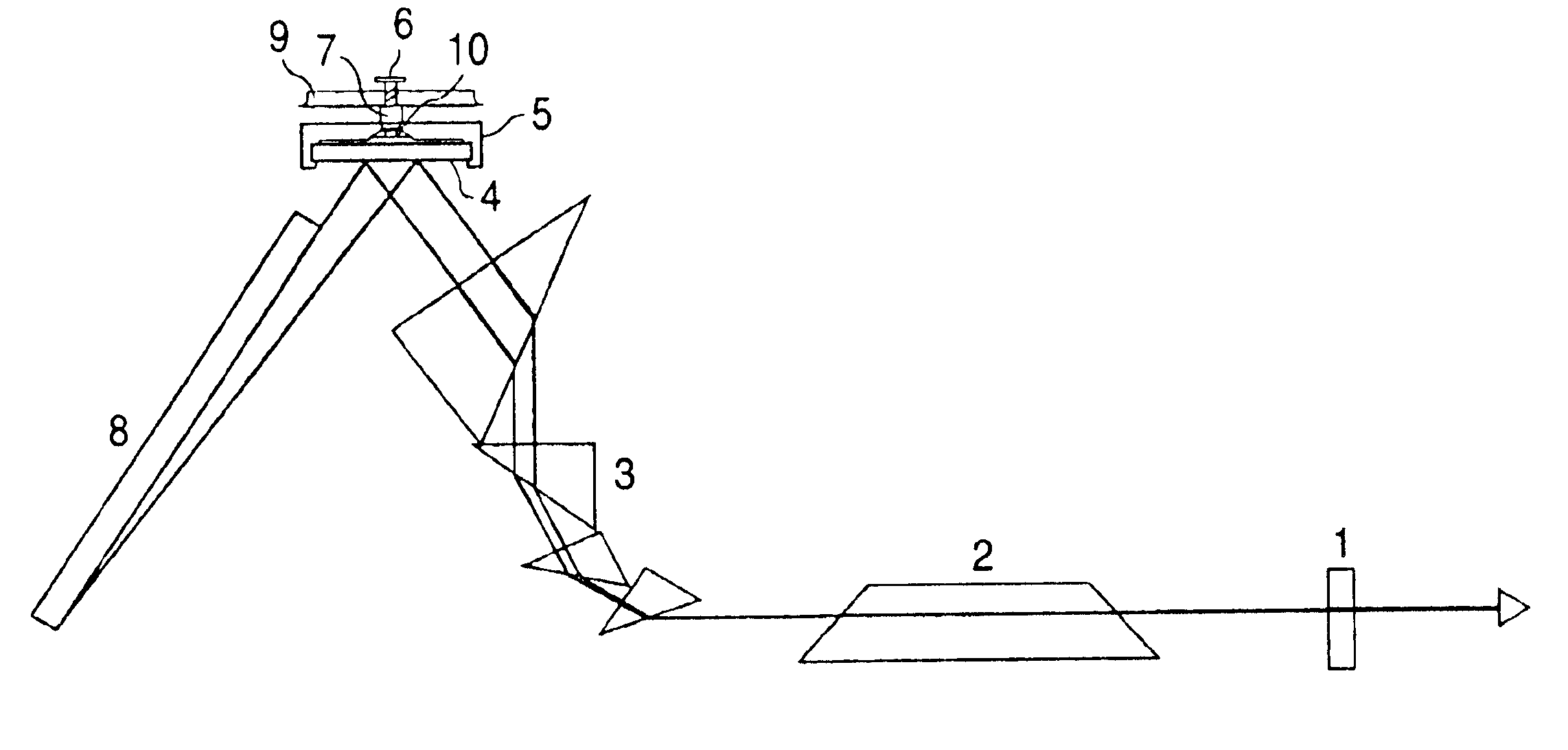
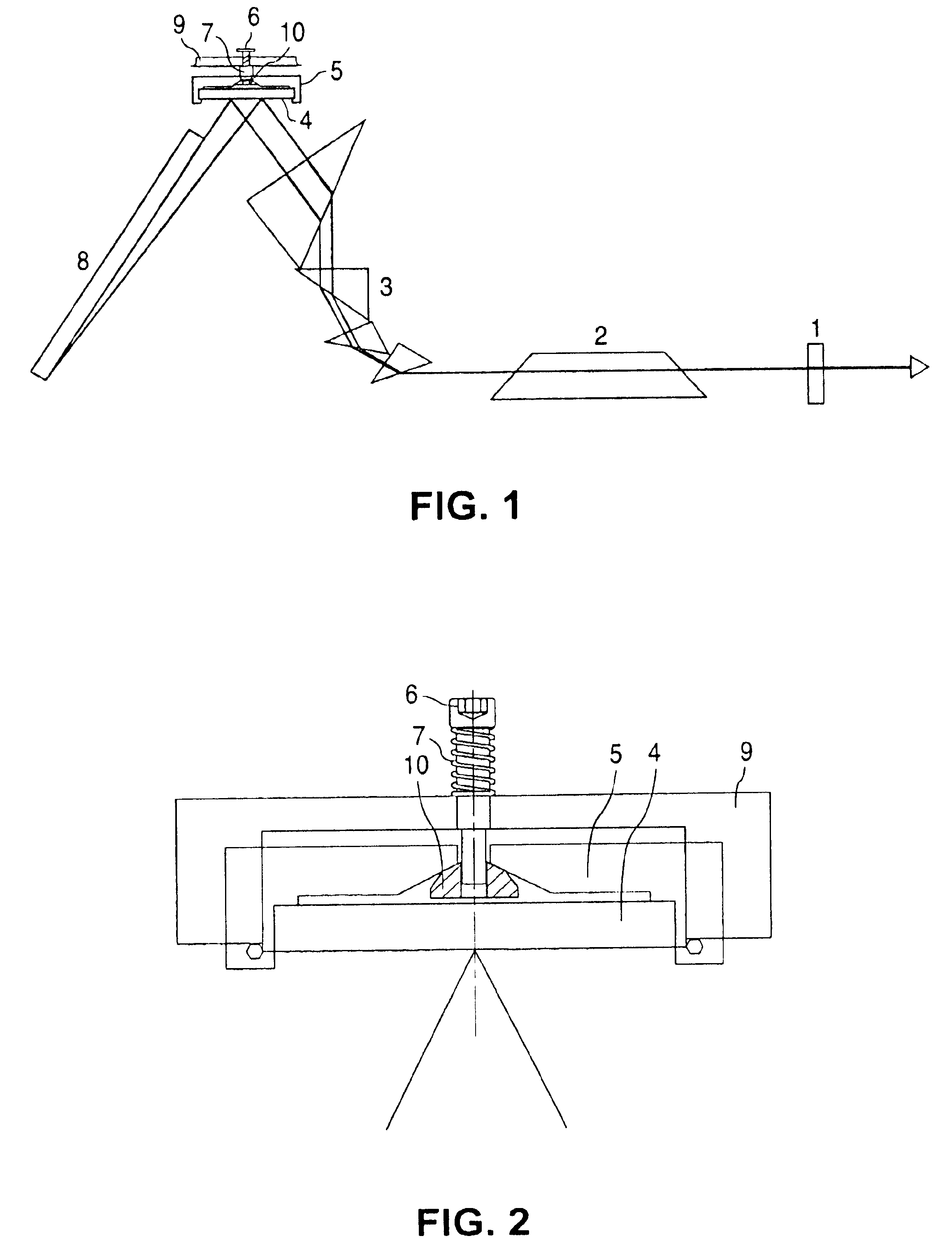
Resonator arrangement for bandwidth control
a bandwidth control and resonance arrangement technology, applied in the direction of electrical equipment, laser details, active medium materials, etc., can solve the problems of time dependent variation of the spectral distribution, difficult production of achromatic imaging optics for this wavelength region, and undesirable wavefront distortion of laser beams
- Summary
- Abstract
- Description
- Claims
- Application Information
AI Technical Summary
Benefits of technology
Problems solved by technology
Method used
Image

Examples
Embodiment Construction
>H. S. Albrecht, P. Heist, J. Kleinschmidt, Laser for generating narrow band radiation, Gebrauchsmusteranmeldung, 1999
[0030]U.S. patent application Ser. Nos. 09 / 452,353, 60 / 235,116, 09 / 317,695, 09 / 244,554, 09 / 602,409, 09 / 599,130, 09 / 598,552, 09 / 629,256, 09 / 769,019, 09 / 791,496, 09 / 771,366, 09 / 738,849, 09 / 715,803, 09 / 718,809, 09 / 712,367, 09 / 843,604, 09 / 883,127, 09 / 900,703, 09 / 775,778, 09 / 791,431, 09 / 694,246, 60 / 280,398, 60 / 212,257, 60 / 244,744, 60 / 242,602, 60 / 267,567, 60 / 281,433, 60 / 296,947, 60 / 309,939 and 09 / 776,589, which are assigned to the same assignee as the present application; and
[0031]German utility model no. 298 22 082.2 (Feb. 2, 1999), J. Kleinschmidt;
[0032]German Patent publications DE 298 22 090, DE 298 22 082, and DE 42 25 781; and
[0033]PCT published application no. WO 01 / 18923 A1.
DETAILED DESCRIPTION OF THE PREFERRED EMBODIMENTS
[0034]Resonator arrangements for regulating or controlling the spectral bandwidth of an excimer or molecular fluorine laser system are set forth ...
PUM
 Abstract
Description
Claims
Application Information