Portable wireless unit

a wireless unit and wireless technology, applied in the direction of substation equipment, substantially flat resonant elements, resonance antennas, etc., can solve the problems of reducing radiation efficiency (antenna efficiency), unable to efficiently use space, and difficult to get sufficient frequency bands, so as to reduce the size of the first plane antenna, increase the effective antenna area, and reduce the effect of space in the cas

Inactive Publication Date: 2005-02-15
LENOVO INNOVATIONS LTD HONG KONG
View PDF13 Cites 55 Cited by
  • Summary
  • Abstract
  • Description
  • Claims
  • Application Information

AI Technical Summary

Benefits of technology

According to this arrangement, the first plane antenna and second plane antenna do not exhibit an independent resonance function, but instead function together to resonate at the desired frequency. The resonance frequency of the first plane antenna is reduced below the desired frequency when the first and second plane antennas are coupled. Accordingly, the size of the first plane antenna may be reduced below the size it would have if it alone produced the desired frequency. The smaller...

Problems solved by technology

Therefore, there occur problems that it becomes difficult to install its internal parts inside the case, it becomes difficult to get the sufficient frequ...

Method used


Image

  • Portable wireless unit
  • Portable wireless unit
  • Portable wireless unit

Examples


embodiment

[Embodiment]

FIG. 6 shows an embodiment of a plane antenna type of FIG. 4(a) A plane antenna 51 comprises a radiation plate 51a disposed on the surface of the upper case 1, a folding part 51b formed by folding and bending to one side of the radiation plate 51a, short-circuit plates 51c, 51d formed at other side of the radiation plate 51a, and a spacer 51e for insulating and holding the folding part 51b. The folding part 51b is provided for forming an electrostatic capacity, and the short-circuit plates 51c, 51d function as the stabs for determining the resonance frequency.

The dimensions of the parts in the case of desired frequency of 2 GHz are as follows: the circuit board 4 measures 120 mm×35 mm, the radiation plate 51a is 10 mm in length L and 7 mm in width W, the height H of the short-circuit plates 51c, 51d is 5 mm, the horizontal plane length d of the folding part 51b is about 7 mm, and the thickness t of the spacer 51e is 1 mm. The resonance frequency of the plane antenna 51 d...


PUM


Abstract

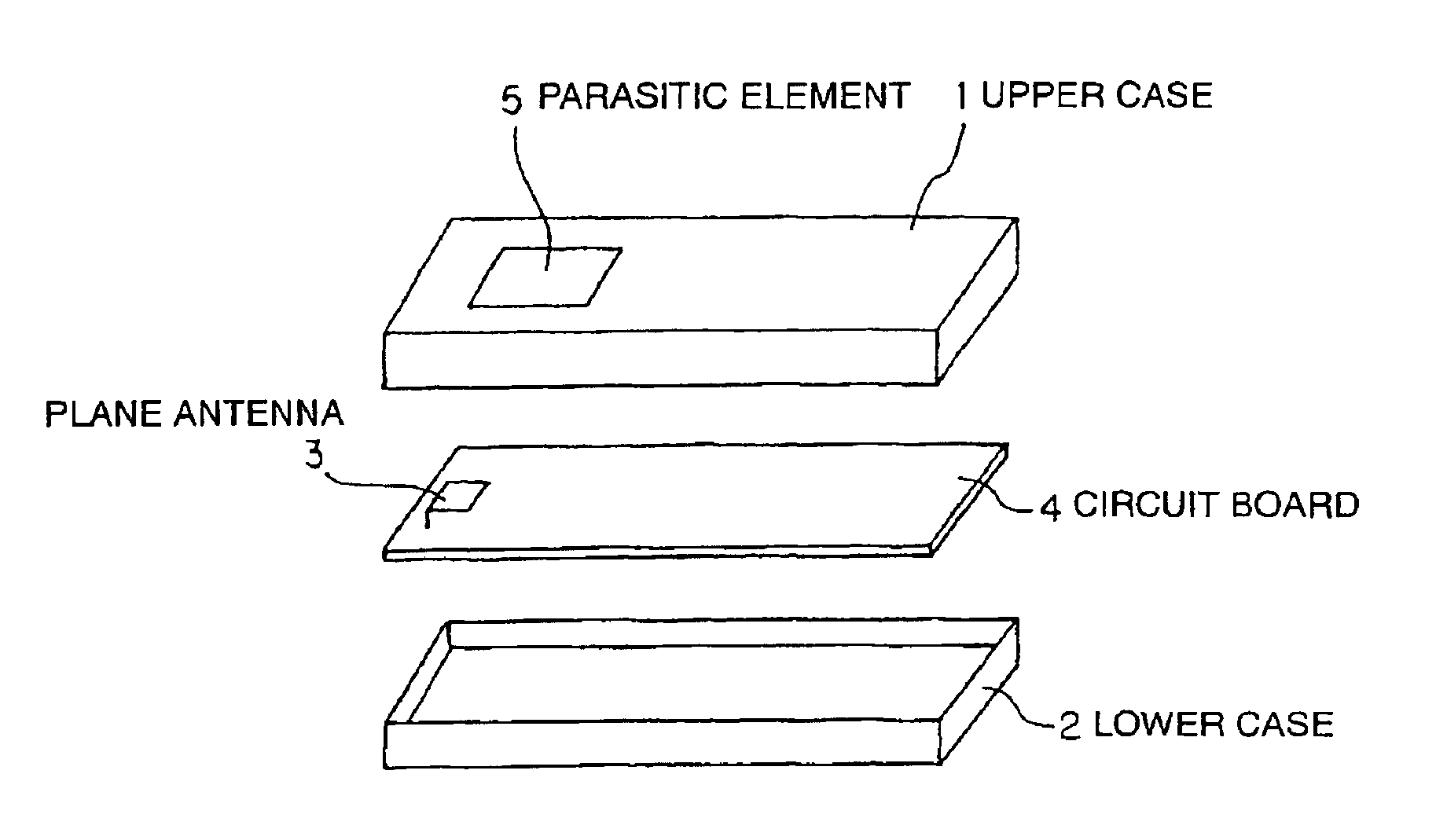
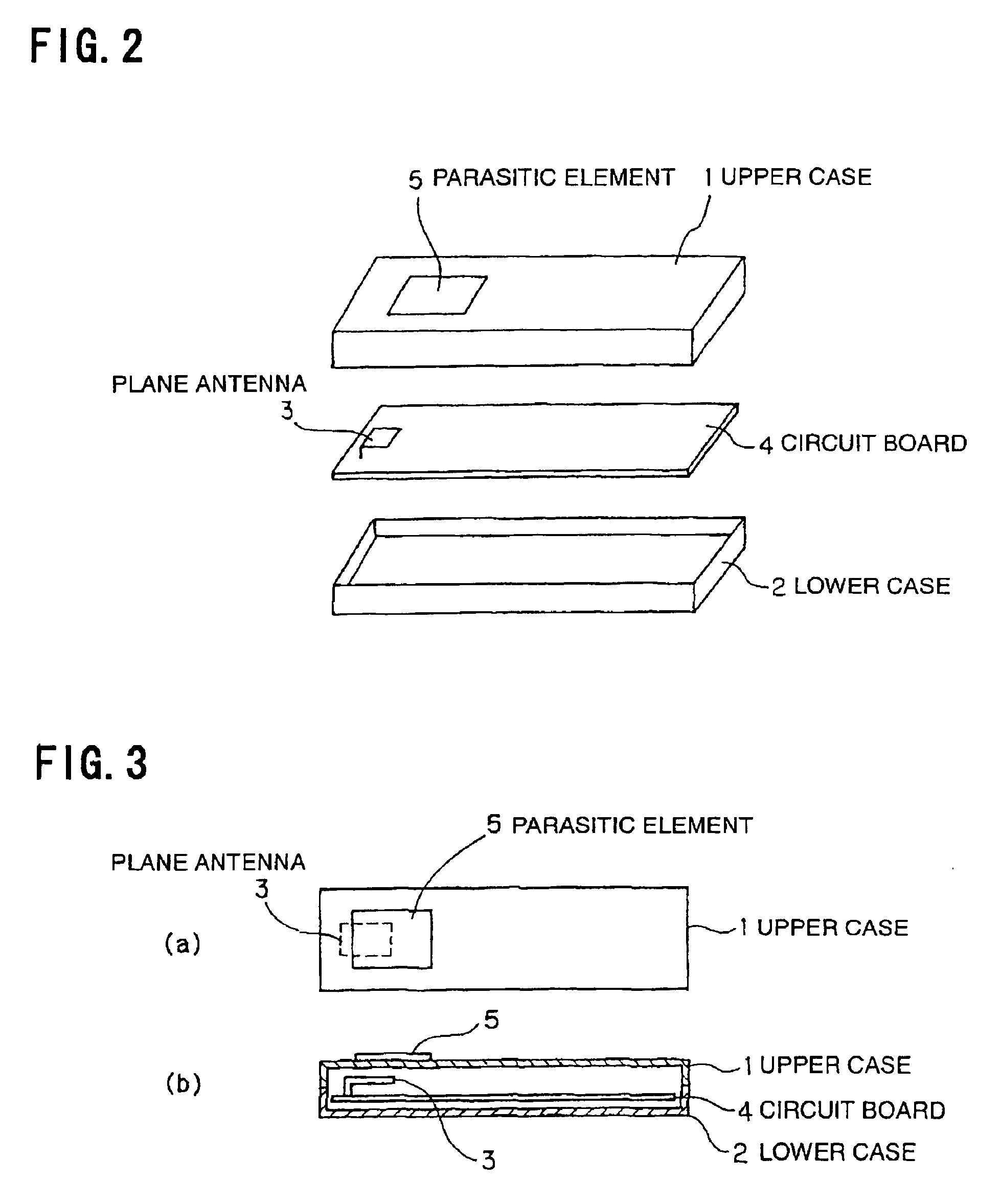
A portable wireless unit of the invention has a first plane antenna smaller than an antenna size determined by a desired frequency, and a second plane antenna presenting an antenna size determined by the desired frequency on the whole by coupling with the first plane antenna.

Description

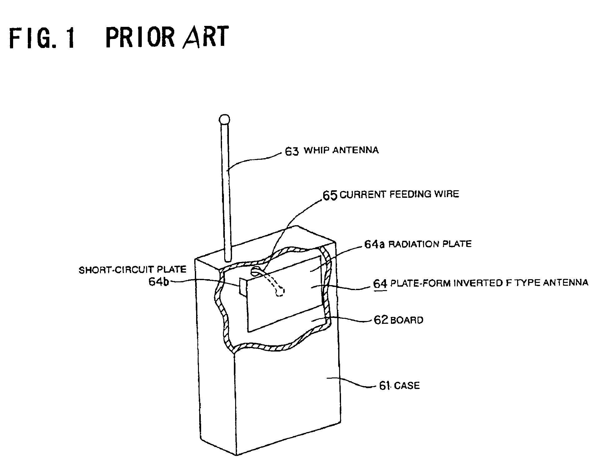
FIELD OF THE INVENTIONThe present invention relates to a portable wireless unit, and more particularly to a portable wireless unit, e.g. cellular phone, using a plane antenna such as plate-form inverted F type antenna.BACKGROUND OF THE INVENTIONMost of handy-type portable wireless units used in a gigahertz band are provided a whip antenna that is accommodated in the case, or a plane antenna such as a plate-form inverted F type antenna that is built in the case.FIG. 1 shows a cellular phone, which is one of the conventional portable wireless units.In a case 61, a circuit board 62 mounting the transmission and reception circuit (not shown) is accommodated, and numeric keys, function keys and liquid-crystal display (neither shown) are provided on the front side (backside of the case 61 in the drawing) of the case 61 formed by resin molding, and a whip antenna 63 (for transmission and reception), which can be retracted in the case 61, in flexible structure is disposed in the upper part ...

Claims


Application Information

Patent Timeline
IPC IPC(8): H01Q1/36H01Q9/04H01Q19/00H01Q1/24H01Q13/08
CPCH01Q1/243H01Q1/36H01Q19/005H01Q9/0421H01Q9/0407
Inventor ITOH, RYOH
Owner LENOVO INNOVATIONS LTD HONG KONG
Why Eureka
Try Eureka