
Tire manufacturing method for improving the uniformity of a tire

a manufacturing method and tire technology, applied in the field of tire manufacturing method, can solve the problems of removing wearable tread rubber from the product, requiring an extra manufacturing step, and affecting the ride and handling of the vehicle,

Active Publication Date: 2005-02-15
MICHELIN RECH & TECH SA
View PDF12 Cites 41 Cited by
  • Summary
  • Abstract
  • Description
  • Claims
  • Application Information

AI Technical Summary

Benefits of technology

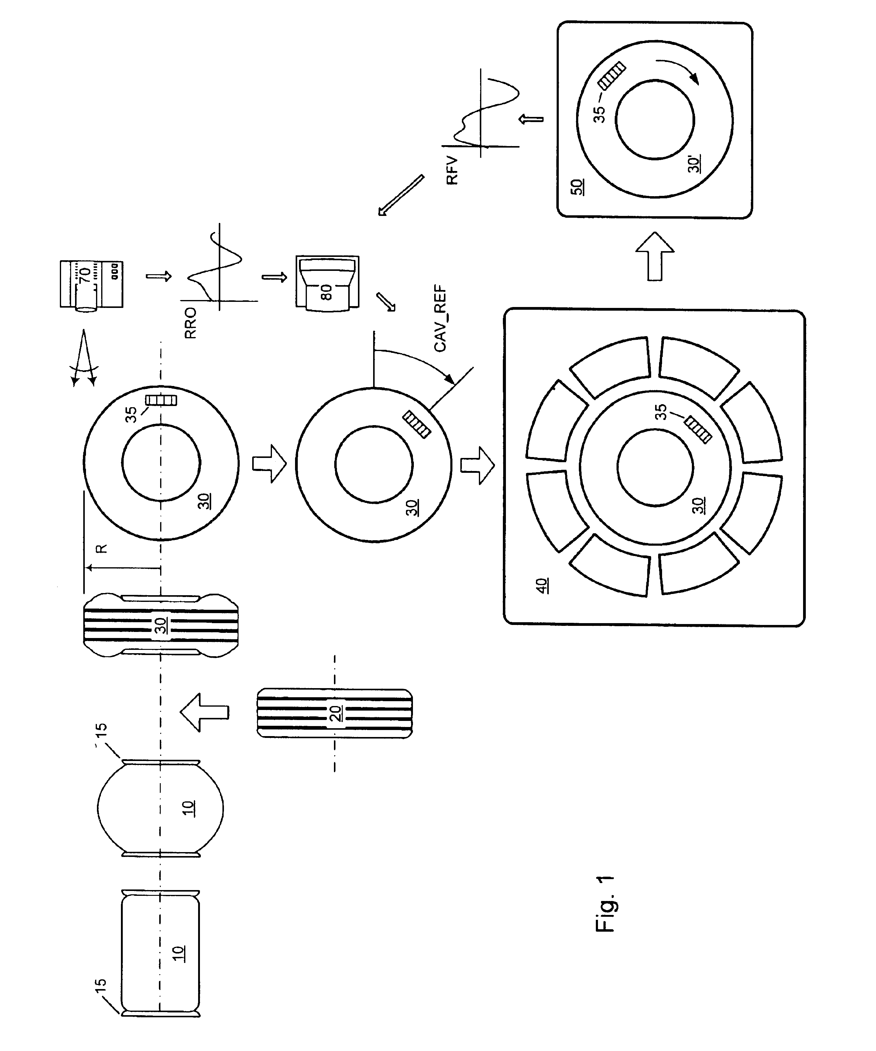
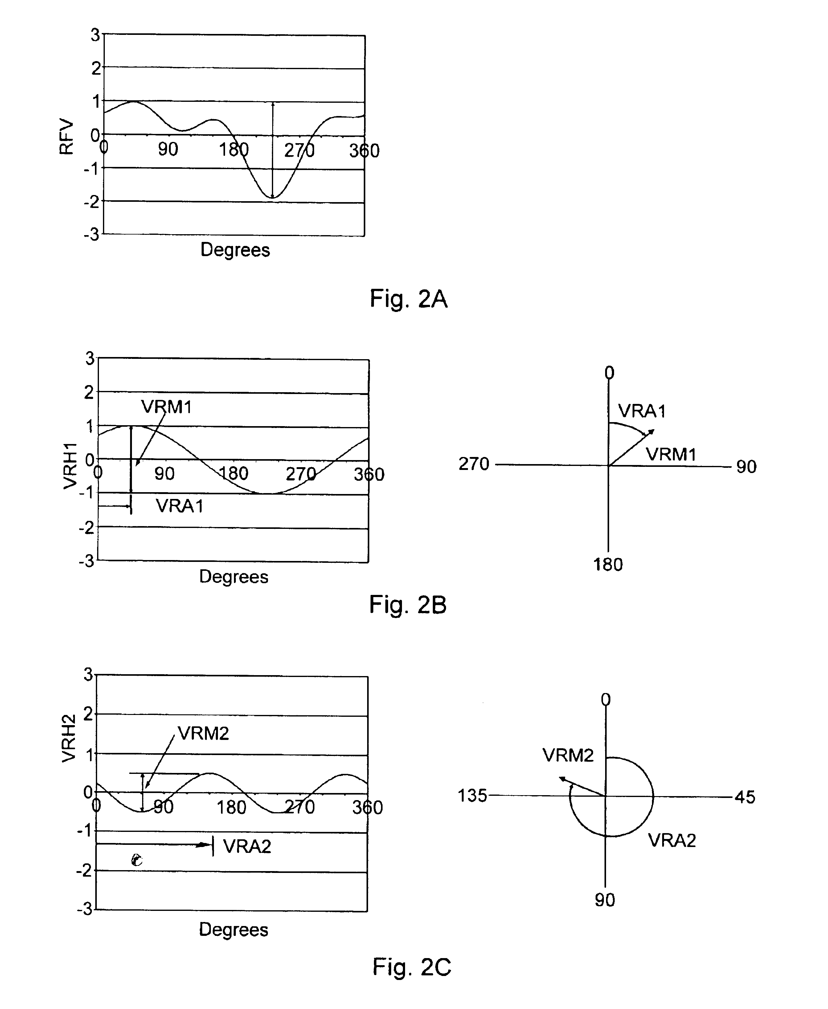
In view of the above background, the present invention provides a tire manufacturing method that can effectively reduce the after cure radial force variation (RFV) of each tire produced. The method of the present invention operates to independently optimize each harmonic of RFV. A composite RFV signal, such as those described above, is a scalar quantity that is the variation of the tire's radial force at each angular position around the tire from the average radial force corresponding to the vertical load applied to the tire. When this composite is decomposed into its respective harmonic components, each harmonic of RFV can be expressed in polar coordinates as an after cure RFV vector. This vector has a magnitude equal to the peak-to-peak magnitude of the force variation of the respective harmonic and an azimuth equal to the angular difference between the measuring reference point and the point of maximum RFV.
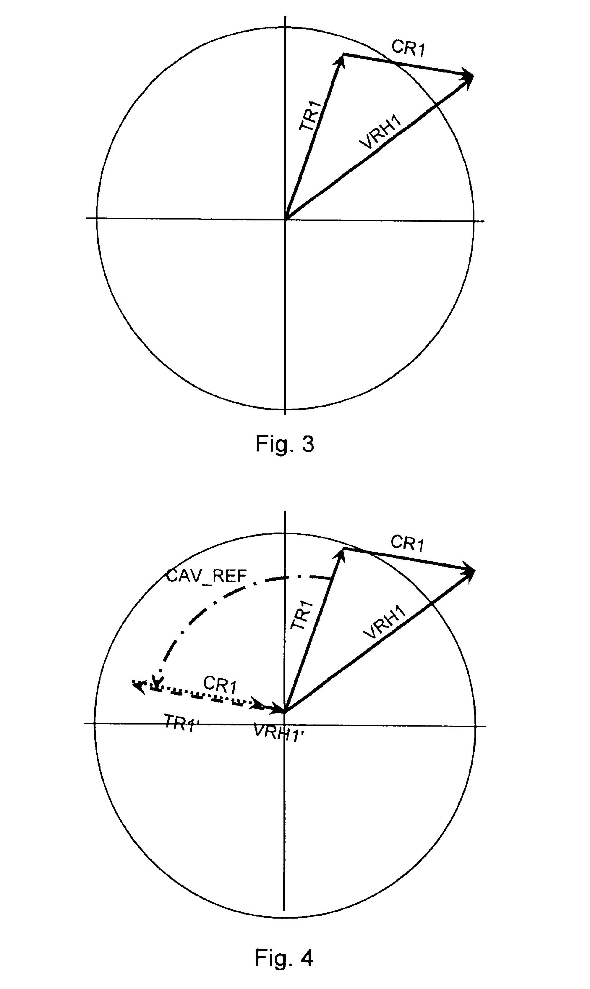
The present invention further improves on previously described methods since it does not rely on manipulation of the measured, composite RFV waveforms to estimate the tire room and curing room effects and does not rely on any of the previously described assumptions. The present invention uses the aforementioned measured data as input to a single analysis step. Thus, the coefficients of all the sub-vectors are simultaneously determined. Once these coefficients are known, the tire room effect vector and curing room effect vector are easily calculated. The method of the invention accounts for the possible RRO of the building drum itself. When any of the previously described methods measure the RRO of a green tire, the measured RRO is the sum of the actual green tire RRO and the RRO of the measuring device upon which the tire is currently mounted, be it a building drum or a measurement apparatus. In summary, the first step of the method determines a set of vector coefficients corresponding to the after cure radial force variation of a tire and comprises the steps of:(a) recording a loading angle of a tire carcass on a measurement fixture,(b) measuring the before cure radial runout of a plurality of finished tires,(c) recording a loading angle of said finished tires in a curing mold and curing said tires,(d) measuring the after cure radial force variation for each of said tires,(e) extracting at least one harmonic of radial runout and of the radial force variation of said tires,(f) determining a set of vector coefficients relating the before cure radial runout to the after cure radial force variation of said tires cured in said mold,(g) storing said vector coefficients,
The method of the invention just described further improves on previous methods in its treatment of the factors that relate before cure RRO to after cure RFV. It has been found that RRO variations on the before cure tire do not always produce an after cure RFV contribution that is a scalar multiple of the RRO vector either in magnitude or azimuth. Thus, a scalar representation that relies on a simple stiffness factor can lead to erroneous result. In the present invention method, the contribution to after cure RFV is modeled as the vector product of a gain vector and the RRO vector. The gain vector correctly models the transformation from before cure RRO to after cure RFV. At least one pair of vector coefficients corresponds to the gain vector.
The method of the invention has an additional advantage owing to its simultaneous determination of the sub-vectors. Unlike previous methods, the method of the invention does not require any precise angular increments of the loading positions to determine the sub-vectors. This opens the possibility to continuously update the sub-vector coefficients using the measured data obtained during the production runs. Thus, the method will take into account production variables that arise during a high volume production run.

Problems solved by technology

When the radial force variation in a cured tire exceeds acceptable limits, the result may be unwanted vibrations affecting the ride and handling of the vehicle.
This method is effective, but has the drawback of creating an undesirable surface appearance and of removing wearable tread rubber from the product.
In addition, this method requires an extra manufacturing step and uses expensive equipment.
This method eliminates the undesirable removal of tread rubber, but still requires an extra manufacturing step and high-cost equipment.
A major drawback to this method is its assumption that the formation and vulcanization contributions to after cure RFV are equivalent for each tire.
In fact, these methods contain contradictory assumptions.
Since, the above methods use composite waveforms including all harmonics, these methods fail to optimize the RFV harmonics to which the vehicle is most sensitive.
In this instance, the tire can cause more vehicle vibration problems than if the process were not optimized at all.

Method used


Image

  • Tire manufacturing method for improving the uniformity of a tire
  • Tire manufacturing method for improving the uniformity of a tire
  • Tire manufacturing method for improving the uniformity of a tire

Examples


Embodiment Construction

Reference will now be made in detail to exemplary versions of the invention, one or more versions of which are illustrated in the drawings. Each described example is provided as an explanation of the invention, and not meant as a limitation of the invention. Throughout the description, features illustrated or described as part of one version may be usable with another version. Features that are common to all or some versions are described using similar reference numerals as further depicted in the figures.

Modern pneumatic tires are generally manufactured with great care and precision. The tire designer's goal is that the finished tire is free of non-uniformity in either the circumferential or lateral directions. However, the designer's good intentions notwithstanding, the multitude of steps in the tire manufacturing process can introduce a variety of non-uniformities. An obvious non-uniformity is that the tire may not be perfectly circular (radial runout or RRO). Another form of non...


PUM

PropertyMeasurementUnit
radial forceaaaaaaaaaa
loading angleaaaaaaaaaa
surface appearanceaaaaaaaaaa

Abstract

A tire manufacturing method includes a method for optimizing the uniformity of a tire by reducing the after cure radial force variation. The after cure radial force variation vector is modeled as a vector sum of each presenting contributions arising from the tire building steps—the “tire room effect vector” and a vector representing contributions arising from the vulcanization and uniformity measurement steps—the “curing room effect vector.” In further detail, both the tire room and curing room effect vectors can be further decomposed into sub-vectors representing each radial force variation contribution for which a measurable indicator is available. For a series of tires, the method obtains such measurements as the before cure radial runout (RRO) at one or more stages of the building sequence, measurements of loading angles on the tire building equipment, and measurements made during vulcanization process.

Description

BACKGROUND OF THE INVENTIONThe present invention relates to a manufacturing method for tires, more specifically a method for improving the uniformity of a tire by reducing the after cure radial force variation. In a tire, and more precisely, a radial tire, the after cure radial force variation (RFV) can be affected by many variables introduced from the process of assembly of the green (uncured) tire and during curing of the tire. When the radial force variation in a cured tire exceeds acceptable limits, the result may be unwanted vibrations affecting the ride and handling of the vehicle. For these reasons, tire manufacturers strive to minimize the level of radial force variation in the tires delivered to their customers.A well-known and commonly practiced method to improve the after cure RFV is to grind the tread surface of the tire in the zones corresponding to excess radial force. This method is effective, but has the drawback of creating an undesirable surface appearance and of r...

Claims


Application Information

Patent Timeline
Patent Type & Authority Patents(United States)
IPC IPC(8): B29D30/06
CPCB29D30/0662B29D2030/0665
Inventor MAWBY, WILLIAM DAVIDO'BRIEN, GEORGE P.PERSYN, EUGENE MARSHALLTRAYLOR, JAMES MICHAEL
Owner MICHELIN RECH & TECH SA
Learn More