Voice encoding/decoding device

a voice coding and decoding technology, applied in the field of voice coding/decoding apparatus, can solve the problems of insufficient number of pulses, disadvantageous disadvantageous amount of operation, and enormous amount of operation

Inactive Publication Date: 2005-02-15
NEC CORP
View PDF19 Cites 7 Cited by
  • Summary
  • Abstract
  • Description
  • Claims
  • Application Information

AI Technical Summary

Problems solved by technology

However, in the prior arts described above, an enormous amount of operation is required to select an appropriate sound source code vector from the sound source code book.
As a result, the remarkably enormous amount of operation is disadvantageously required.
However, although preferable sound quality can be obtained at a bit rate of 8 kB / S or more, when a bit rate lower than the value, and when background noise is superposed on voice, the number of pulses is not sufficient, and the sound quality of a background noise component of coded voice is considerably degraded.
However, since pulses must be raised at random for a random signal such as background noise, it is difficult that the background noise can be preferably represented by a small number of pulses.

Method used


Image

  • Voice encoding/decoding device
  • Voice encoding/decoding device
  • Voice encoding/decoding device

Examples


first embodiment

(First Embodiment)

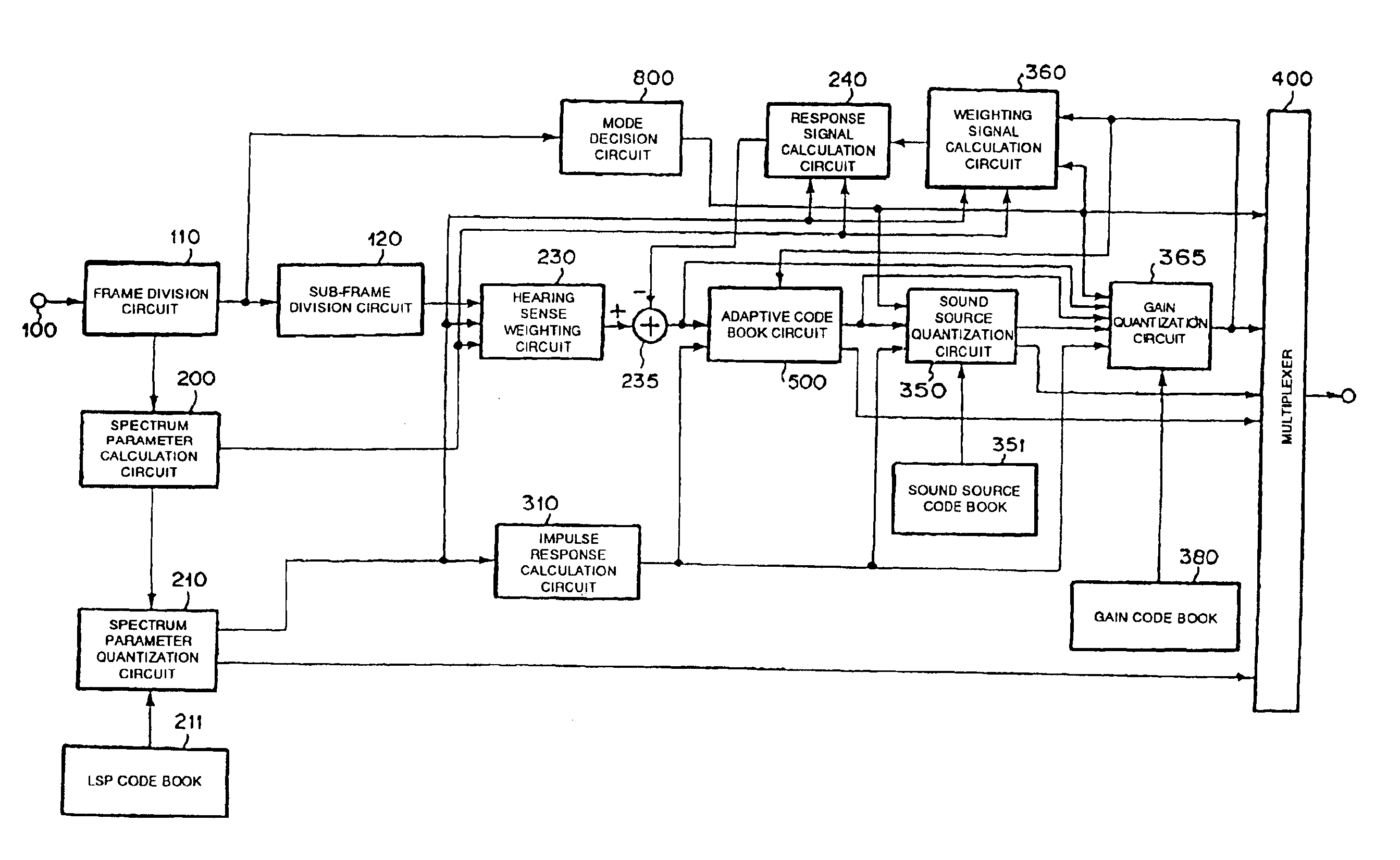
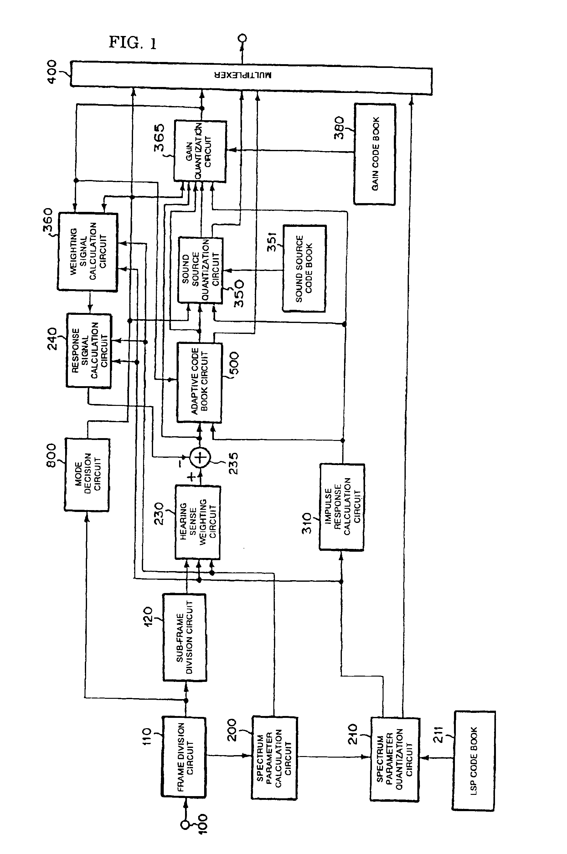
FIG. 1 is a block diagram of a voice coding apparatus according to the present invention. In FIG. 1, a voice signal is input from an input terminal 100, and the voice signal is divided by a frame division circuit 110 every frame (for example, 20 mS). In a sub-frame division circuit 120, the voice signal of the frame is divided into sub-frames each of which is shorter than the frame (for example, 5 mS).

In a spectrum parameter calculation circuit 200, a windows which is longer than a sub-frame length (for example, 24 mS) is applied to the voice signal of at least one sub-frame to cut a voice, and the spectrum parameter is raised to the power of a predetermined number (for example, P=10th). In the calculation of the spectrum parameter, the known LPC analysis, a BURG analysis, and the like can be used. In this case, it is assumed that the BURG analysis is used. The details of the Burg analysis are described in “Signal Analysis and System Identification” by Nakamizo (pp...

second embodiment

(Second Embodiment)

FIG. 19 is a block diagram of another coding apparatus according to the present invention. Since constituent elements in FIG. 19 to which the same reference numerals as in FIG. 1 are added perform the same operations as in FIG. 1, a description thereof will be omitted. In FIG. 19, the operation of a sound source quantization circuit 355 is different from that of FIG. 1. In this case, when mode decision information is Mode 0, a position generated according to a predetermined rule is used as a position of a pulse.

For example, the positions of pulses the number of which are predetermined (for example, M1) are generated by a random number generation circuit 600. More specifically, M1 numeral values generated by the random number generator are considered as the positions of pulses. In addition, the plural sets of positions of different types are generated. The M1 positions of the plural sets generated as described above are output to the sound source quantization circu...

third embodiment

(Third Embodiment)

FIG. 21 is a block diagram of a decoding apparatus according to the present invention. This decoding apparatus may be combined to the coding apparatus shown in FIG. 1 to form a coding / decoding apparatus. In FIG. 21, a demultiplexer 500 receives mode decision information, an index representing a gain code vector, an index representing delay of an adaptive code book, information of a sound source signal, an index of a sound source code vector, and an index of a spectrum parameter from a received signal, and separately outputs the respective parameters.

A gain decoding circuit 510 receives the index of the gain code vector and the mode decision information, and reads and outputs a gain code vector from the gain code book 380 depending on the index.

An adaptive code book circuit 520 receives the mode decision information and the delay of the adaptive code book, generates an adaptive code vector, and multiples the gain code vector by the gain of the adaptive code book to ...


PUM


Abstract

A voice coding apparatus which can obtain preferable sound quality at a low bit rate is provided. In a mode decision circuit 800 of the voice coding apparatus, a mode is decided from an input voice signal by using a characteristic amount every sub-frame. In a sound source quantization circuit 350, in case of a predetermined mode, the amplitude or polarity of a non-zero pulse is calculated in advance. Further, combinations of a plurality of shift amounts by which the position of a predetermined pulse is time-shifted and a gain code vector for quantizing a gain are searched. Finally, the combination which minimizes distortion between a reproduced voice and an input voice is selected.

Description

TECHNICAL FIELDThe present invention relates to a voice coding / decoding apparatus for coding a voice signal at a low bit rate with high quality.BACKGROUND ARTAs a method of efficiently coding a voice signal, for example, a CELP (Code exited linear predictive coding) described in “Code-exited linear prediction: High quality speech at very low bit rates” by M. Schroeder and B. Atal (Proc. ICASSP, pp. 937-940, 1985) (Reference 1) is known. Further, “Improved speech quality and efficient vector quantization in SELP” by Klein et al., (Proc. ICASSP, pp. 155-158, 1988) (Reference 2) is known. In these prior arts, on a transmission side, a spectrum parameter representing the spectrum characteristics of a voice signal is extracted from a voice signal every frame (for example, 20 mS) by using linear prediction (LPC) analysis. The frame is further divided into sub-frames (for example, 5 mS). Parameters (a delay parameter corresponding to a pitch period and a gain parameter) in an adaptive code...

Claims


Application Information

Patent Timeline
Patent Type & Authority Patents(United States)
IPC IPC(8): G10L19/00G10L19/14G10L19/10G10L19/038G10L19/04G10L19/08G10L19/12G10L19/22H03M7/30H04B14/04
CPCG10L19/18G10L19/10
Inventor OZAWA, KAZUNORI
Owner NEC CORP
Why Eureka
Try Eureka