Fuel vapor separator for internal combustion engine

a technology of internal combustion engine and separator, which is applied in the direction of combustion-air/fuel-air treatment, separation process, lighting and heating apparatus, etc., can solve the problem of extremely limited likelihood of contaminants lodging in the tube coil

Active Publication Date: 2005-02-22
CARTER FUEL SYST
View PDF8 Cites 40 Cited by
  • Summary
  • Abstract
  • Description
  • Claims
  • Application Information

AI Technical Summary

Benefits of technology

The present invention relates to a vapor separator for use with a fuel pump assembly of an internal combustion engine. The vapor separator comprises a hollow chamber having a sidewall with a cylindrical interior surface and a top wall and a bottom wall enclosing the chamber. Fuel is introduced into the chamber through a fuel intake which communicates with a source of fuel so that a constant supply of fuel is supplied to the chamber. Fuel is removed from the chamber through an outlet which is connected to a high pressure fuel pump assembly that pumps the fuel into a fuel distribution system for the internal combustion engine such as a fuel rail and fuel injector combination. A hollow cylindrical tube is configured into a coil having a plurality of circular loops that are dimensioned to fit within the cylindrical interior of the chamber. The tube coil is positioned within the chamber and the first and second ends of the tube extend through the wall of the chamber. A source of coolant liquid is connected to the first end of the tube coil so the coolant can flow through the hollow tube coil within the chamber from the first end to the second end of the tube thereby removing heat from the interior of the chamber.

Problems solved by technology

Consequently, because the diameter of the tube is no less than the upstream diameter of the coolant supply, the likelihood of contaminants lodging in the tube coil is extremely limited.

Method used


Image

  • Fuel vapor separator for internal combustion engine
  • Fuel vapor separator for internal combustion engine
  • Fuel vapor separator for internal combustion engine

Examples


Embodiment Construction

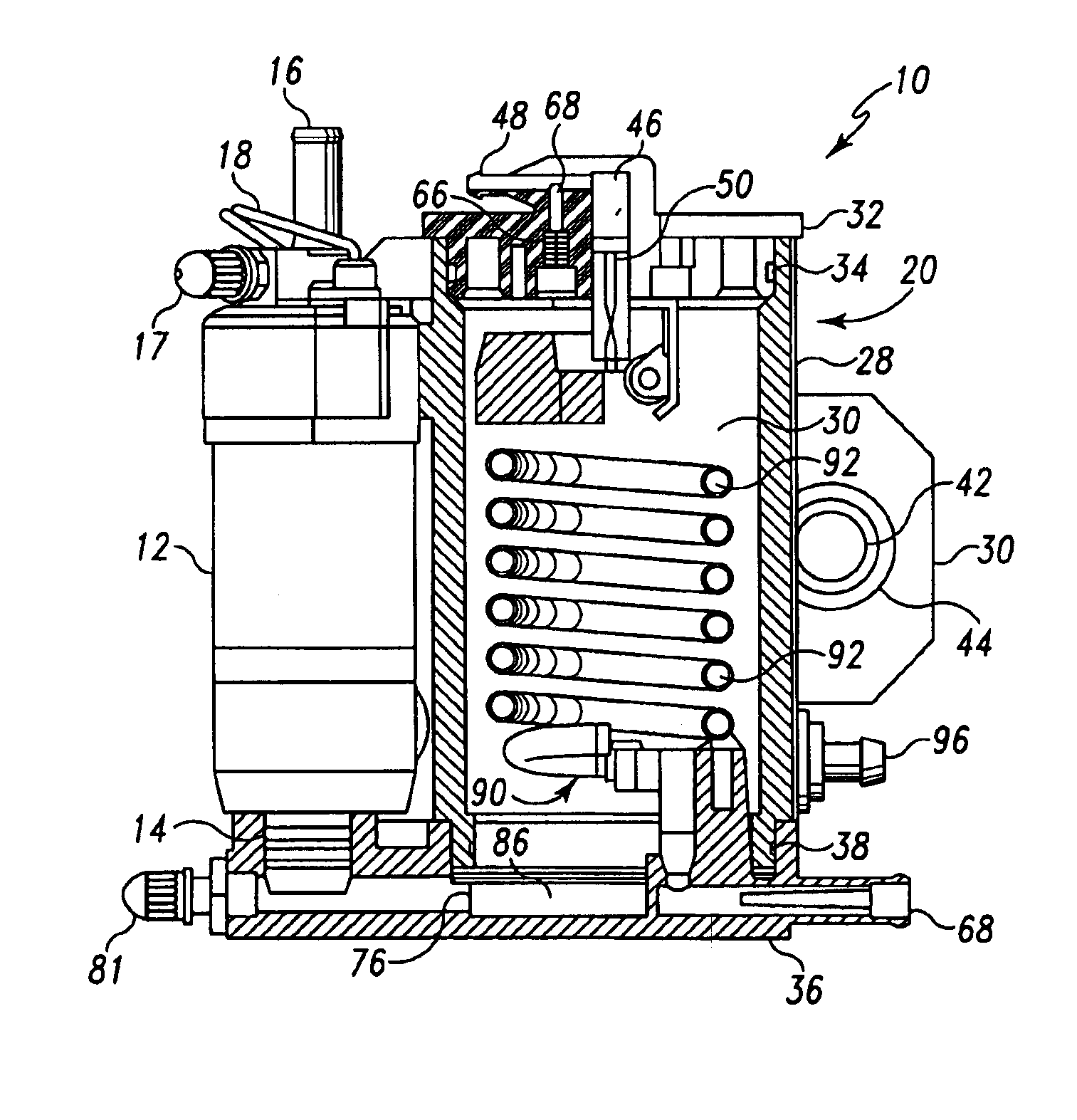
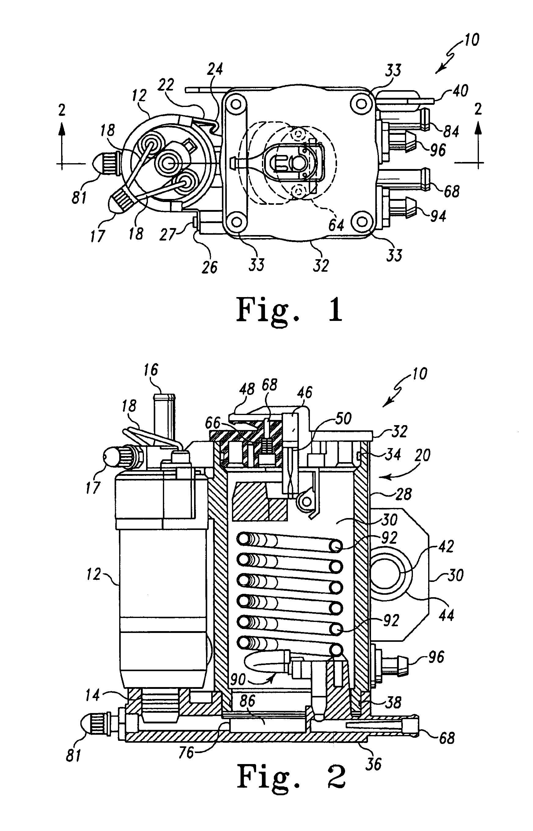
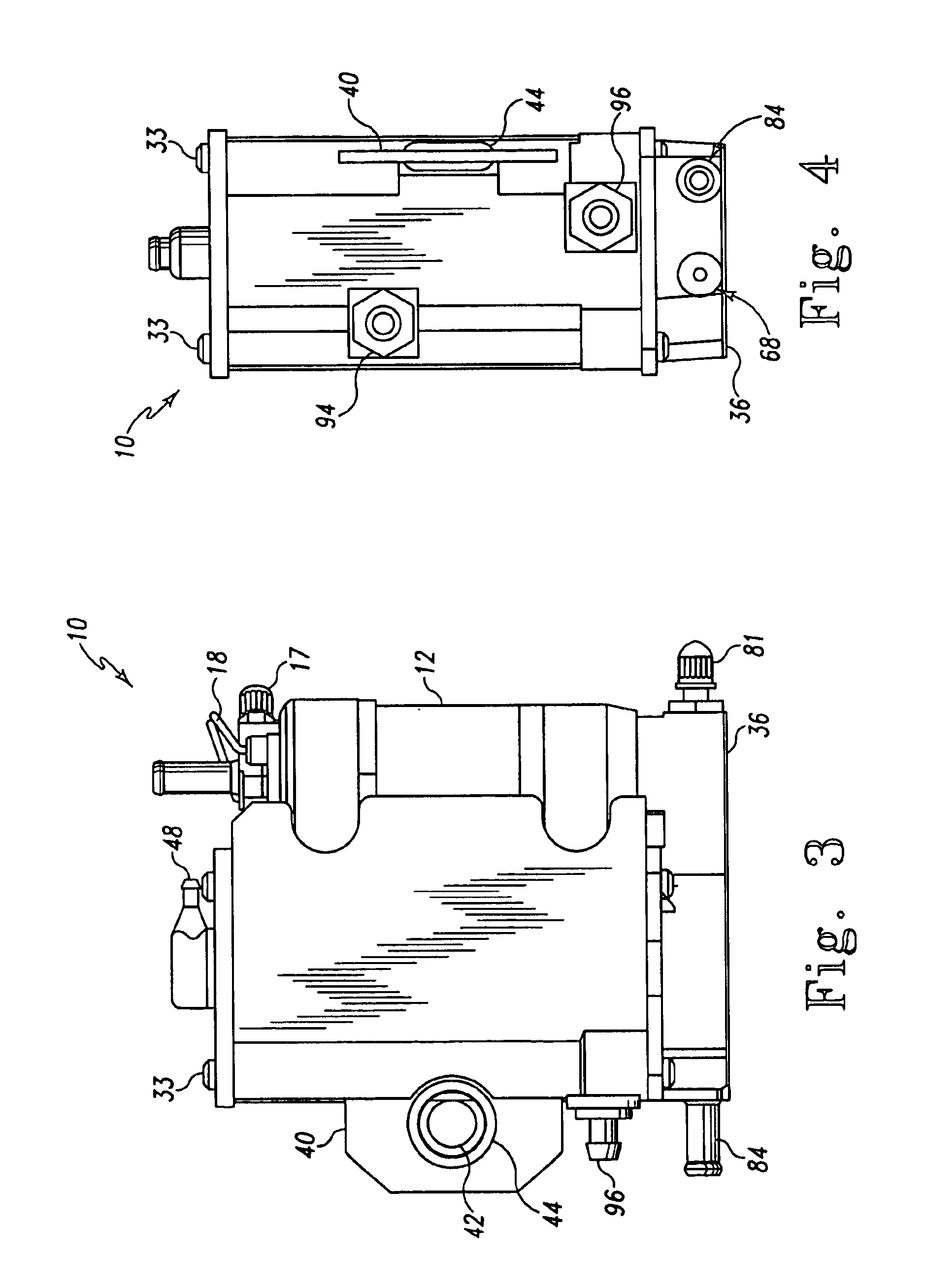
With reference to FIGS. 1, 2, 3 and 4, vapor separator assembly 10 comprises a high pressure fuel pump 12 which includes a fuel intake 14 at the bottom of the pump 12 and a fuel pump outlet 16 at the top of pump 12. Electrical power is supplied to pump 12 through wires 18. A schrader valve 17 is provided at the top of pump 12 to allow pressure testing of the outlet pressure. Outlet 16 is connected to the fuel distribution system of an internal combustion engine such as a fuel rail and injector assembly for a fuel injected internal combustion engine (not shown), and fuel is pumped into the fuel distribution system by pump 12. High pressure fuel pump 12 is mounted to the side of fuel separator assembly 20 by a curved metal strap 22. A hooked end 24 is formed on strap 22 which engages a flange on the side of separator assembly 20. A screw mounting 26 is formed at the other end of strap 22 and a screw 27 secures the strap to assembly 20.

Separator assembly 20 also comprises a hollow cyli...


PUM


Abstract

A fuel separator is disclosed having a hollow interior in which a tubular coiled heat exchanger is positioned to receive a coolant liquid therethrough. Fuel is fed into the chamber through a fuel inlet and pumped out of the chamber by a high pressure pump into the fuel distribution system of an internal combustion engine. Heated excess fuel from the fuel distribution system of an internal combustion engine is returned to the chamber through a fuel return inlet at the bottom of the chamber and the heated fuel passes upwardly through the coolant coil thereby cooling the heated return fuel. Fuel vapor that is not condensed as a result of cooling can escape from the chamber through a float needle valve at the top of the chamber. A pressure relief valve is also provided at the top of the chamber to allow the vapor to escape when a predetermined internal pressure is reached.

Description

BACKGROUND OF THE INVENTIONThe present invention is a fuel vapor separator used in a fuel delivery system of an internal combustion engine, and more particularly, a fuel vapor separator for a Marine engine which uses water drawn into the engine from the Marine lake or sea water environment of engine operation for cooling purposes. It is a long recognized problem in the internal combustion engine art that heat build-up of an engine can adversely effect the fuel supply system of the engine thereby causing the fuel to vaporize before it is introduced into the engine's combustion chambers. This condition, commonly referred to as vapor lock, can not only have a damaging effect upon engine components but can result in poor engine performance, overheating and interrupted engine operation. Fuel vapor is particularly disadvantageous in fuel injected engines. Typically, in fuel injection engines, fuel is introduced into a fuel rail by a high pressure fuel pump before it is injected into the c...

Claims


Application Information

Patent Timeline
Patent Type & Authority Patents(United States)
IPC IPC(8): F02M31/00F02M37/20F02M37/08F02M31/20F28D7/00F28D7/02F02B61/04F02B61/00B01D53/00
CPCB01D53/002F02M31/20F02M37/20F28D7/024F02M37/08F02B61/04Y02T10/126Y02T10/12F02M15/00F02M37/04
Inventor HARVEY, RICHARD W.RICHARDS, MICHAEL S.HAYES, GERALD R.
Owner CARTER FUEL SYST
Why Eureka
Try Eureka