Evaporated-fuel storage system

a technology of evaporation fuel and storage system, which is applied in the direction of machines/engines, liquid handling, packaging goods types, etc., can solve the problems of increasing the size of the entire float valve, small amount of fuel permeation, and fuel permeation through the valve chamber, so as to reduce the size of the float valve, suppress the effect of fuel permeation and minimize the size of the opening

Inactive Publication Date: 2005-02-22
HONDA MOTOR CO LTD
View PDF8 Cites 5 Cited by
  • Summary
  • Abstract
  • Description
  • Claims
  • Application Information

AI Technical Summary

Benefits of technology

Accordingly, it is an object of the present invention to reduce the size of a float valve, and to minimize the size of an opening for mounting the float valve to a fuel tank made of a synthetic resin impermeable to fuel, to suppress fuel permeation.
With this arrangement, the valve chamber of the float valve is disposed separately from the fuel tank above the fuel tank, thereby eliminating limitation in the positional relationship between the filled-up liquid surface in the fuel tank and a valve seat of the float valve. Therefore, it is possible to reduce the vertical dimension of the float valve. Moreover, the size of the opening for mounting the valve chamber to the fuel tank can be minimized, thereby suppressing the permeation of the fuel through the opening in the fuel tank made of a synthetic resin impermeable to the fuel.
With this arrangement, the valve chamber of the float valve is provided adjacent to a fuel supply port in the filler tube. Therefore, the length of the evaporated-fuel return passage connecting the valve chamber and the fuel supply port can be shortened, leading to reductions in the size and weight of the evaporated-fuel return passage and a reduction in amount of permeating fuel.
With this arrangement, the check valve adapted to be opened upon application of the predetermined pressure to the fuel tank is disposed in the second evaporated-fuel passage. Therefore, even if the fuel is supplied little by little through a fuel supply nozzle into the fuel tank after the fuel tank has entered a filled-up state where the float valve closes the first evaporated-fuel passage, the liquid surface in the filler tube can be raised until the pressure in the fuel tank exceeds a pressure for opening the check value. Thus, an automatic stopping device for the fuel supply nozzle can be reliably operated to prevent the fuel from flowing through the second evaporated-fuel passage into the canister. If the internal pressure in the fuel tank in the filled-up state rises due to a rise in temperature or the like, the check valve is opened when the internal pressure exceeds the pressure for opening the check valve, whereby the evaporated fuel can be discharged through the second evaporated-fuel passage into the canister. Further, since the check valve is mounted integrally with the valve chamber of the float valve, reductions in the size and weight of these valves can be achieved, as compared with a case where the check valve is mounted separately from the valve chamber of the float valve.

Problems solved by technology

However, the conventional system suffers from the following problem: If a distance between an upper wall of the fuel tank in which a valve chamber is mounted and a filled-up liquid surface is large depending on the shape of the fuel tank, a distance between a valve seat formed at an upper end of the valve chamber and the float vertically movably accommodated in the valve chamber is large, resulting in an increase in the size of the entire float valve.
However, if a valve chamber of a float valve made of a different material is fitted into and welded to an opening defined in a fuel tank, the valve chamber of the float valve permits a small amount of fuel permeation.
Therefore, even if the fuel tank itself is made of a material impermeable to the fuel, there is a possibility that the fuel permeates through the valve chamber.

Method used


Image

  • Evaporated-fuel storage system
  • Evaporated-fuel storage system
  • Evaporated-fuel storage system

Examples


Embodiment Construction

The present invention will now be described by way of a preferred embodiment with reference to the accompanying drawings.

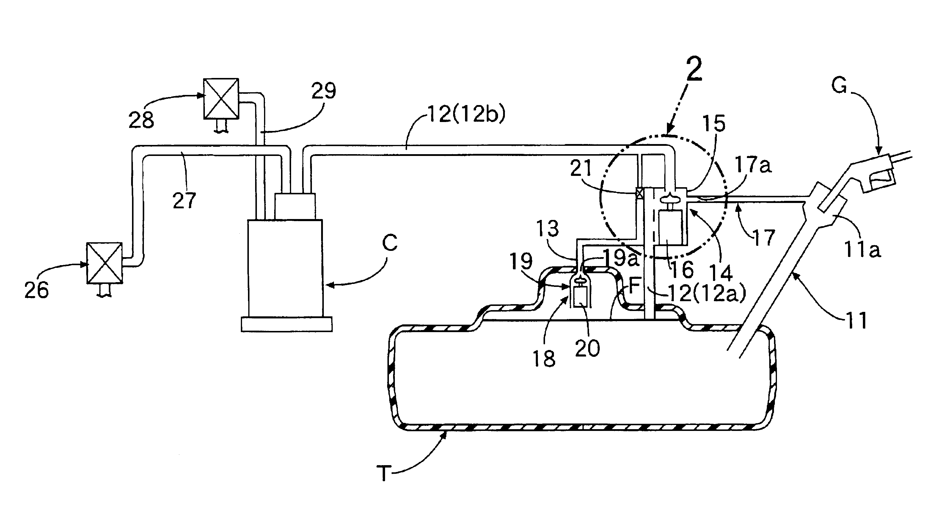
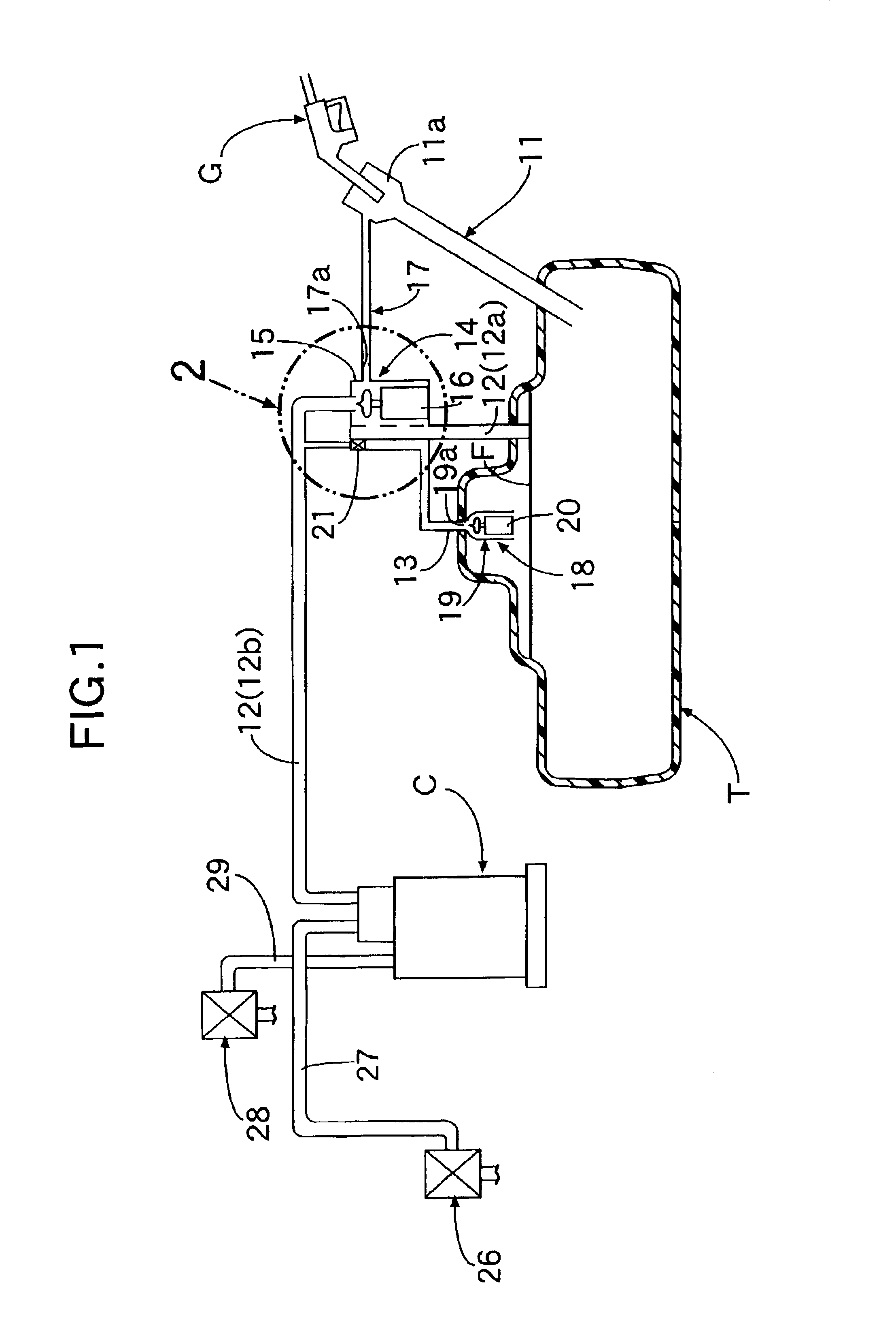
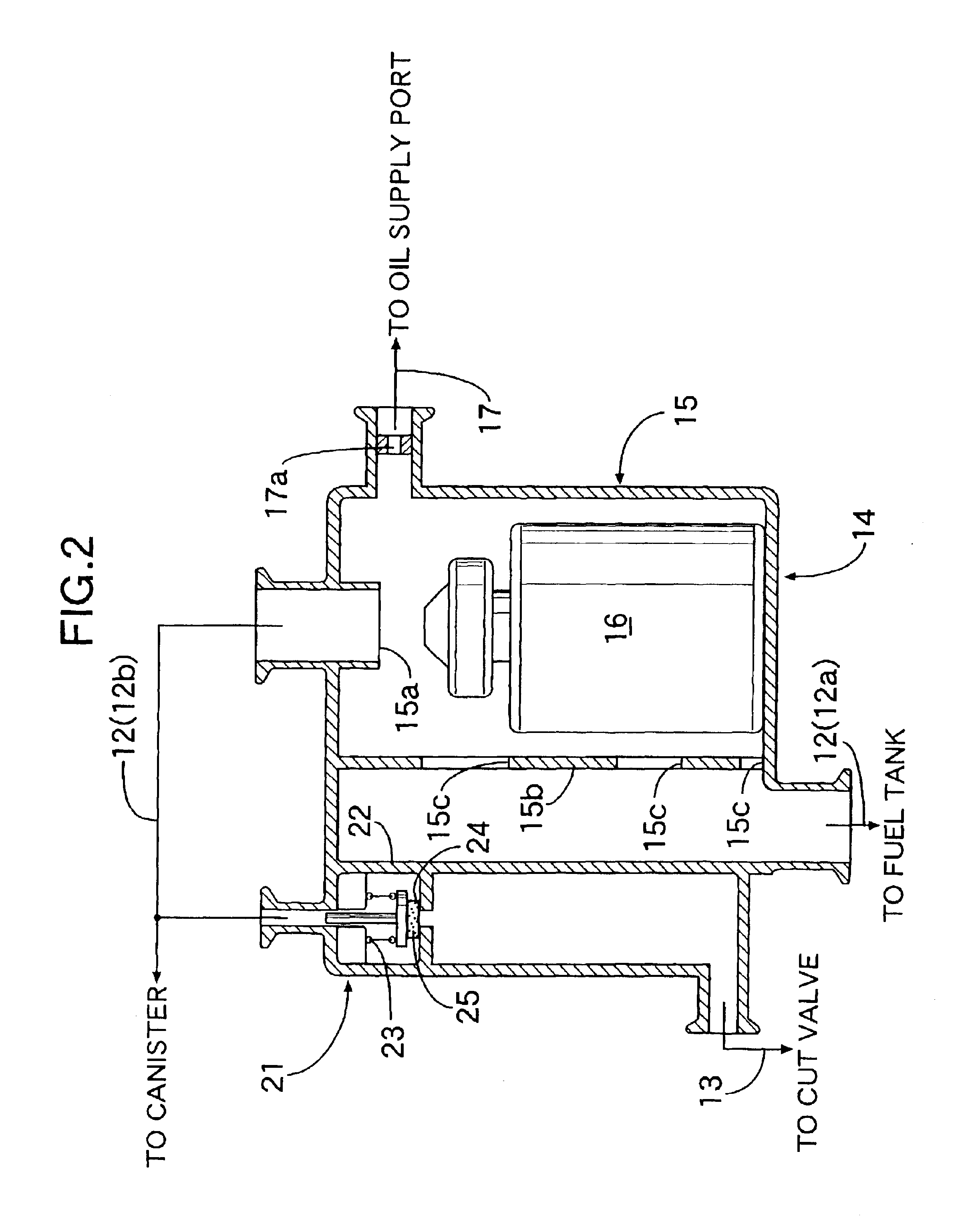
Referring first to FIGS. 1 and 2, a fuel tank T is formed by blow-molding a synthetic resin impermeable to fuel, and includes a filler tuber 11 extending upwards and having a fuel supply port 11a defined at its upper end. An upper space in the fuel tank T and a canister C for adsorbing an evaporated fuel generated in the fuel tank T to suppress the dissipation to the atmosphere, are connected to each other through a first evaporated-fuel passage 12. The first evaporated-fuel passage 12 includes an upstream portion 12a leading to the fuel tank T and a downstream portion 12b leading to the canister C. The upstream portion 12a extends through an upper wall of the fuel tank T, and opens at a level corresponding to a filled-up fuel surface. The upper space in the fuel tank T is connected to the downstream portion 12b of the first evaporated-fuel passage 12 through a se...


PUM

PropertyMeasurementUnit
pressureaaaaaaaaaa
pressureaaaaaaaaaa
sizeaaaaaaaaaa

Abstract

A fuel tank and a canister are connected to each other by a first evaporated-fuel passage and a second evaporated-fuel passage, and a valve chamber of a float valve separate from the fuel tank is disposed at an intermediate portion of the first evaporated-fuel passage. Thus, there is no limitation in the positional relationship between a filled-up liquid surface in the fuel tank and a valve seat of the float valve. Therefore, it is possible to reduce the vertical dimension of the float valve. Moreover, since the valve chamber is provided separately from the fuel tank, it is unnecessary to define an opening for mounting the valve chamber to the fuel tank.

Description

BACKGROUND OF THE INVENTION1. Field of the InventionThe present invention relates to an evaporated-fuel storage system in which a canister adapted to adsorb an evaporated fuel is connected to a fuel tank.2. Description of the Related ArtSuch evaporated-fuel storage systems are known from Japanese Patent Nos. 2808403 and 3158170, their corresponding U.S. Pat. No. 5,606,954, and Japanese Patent Application Laid-open No. 2002-2314 and its corresponding U.S. patent Publication No. US-2001-0054452-A1. In an automobile having such a conventional evaporated-fuel storage system, an upper space in a fuel tank is connected to a canister through an evaporated-fuel passage, and an opening connecting the evaporated-fuel passage to the fuel tank is opened and closed by a float valve. If a liquid surface in the fuel tank is raised by supplying a fuel from a filler tube through a fuel supply nozzle, an evaporated fuel forced out of the fuel tank into the evaporated-fuel passage is adsorbed by the c...

Claims


Application Information

Patent Timeline
Patent Type & Authority Patents(United States)
IPC IPC(8): B60K15/035B60K15/03F02M25/08B60K15/077F02M37/00
CPCB60K15/03519F02M25/0872F02M25/0854F02M25/0836Y10T137/8634
Inventor YANASE, TAIKICHOU, TSUYOSHIGOMA, HISAYUKI
Owner HONDA MOTOR CO LTD
Why Eureka
Try Eureka