Automated reciprocal stacking assembly

Inactive Publication Date: 2005-02-22
FRITZ CHARLES W +1
View PDF6 Cites 6 Cited by
  • Summary
  • Abstract
  • Description
  • Claims
  • Application Information

AI Technical Summary

Benefits of technology

It is an object of the invention to provide improved elements and arrangements thereof for the purposes

Problems solved by technology

The thin, narrow rubber sheets are commonly produced in a continuous manner resulting in an extremely long sheet of rubber.
It is not possible to store, package or transport the rubber in long flat sheets, so the rubber is commonly folded into a multilayer pile and stacked on a pallet for storage and shipping.
The rubber sheet may be folded and stacked onto the pallets by hand, but this is an inefficient process.
Many problems exist with t

Method used


Image

  • Automated reciprocal stacking assembly
  • Automated reciprocal stacking assembly
  • Automated reciprocal stacking assembly

Examples


Embodiment Construction

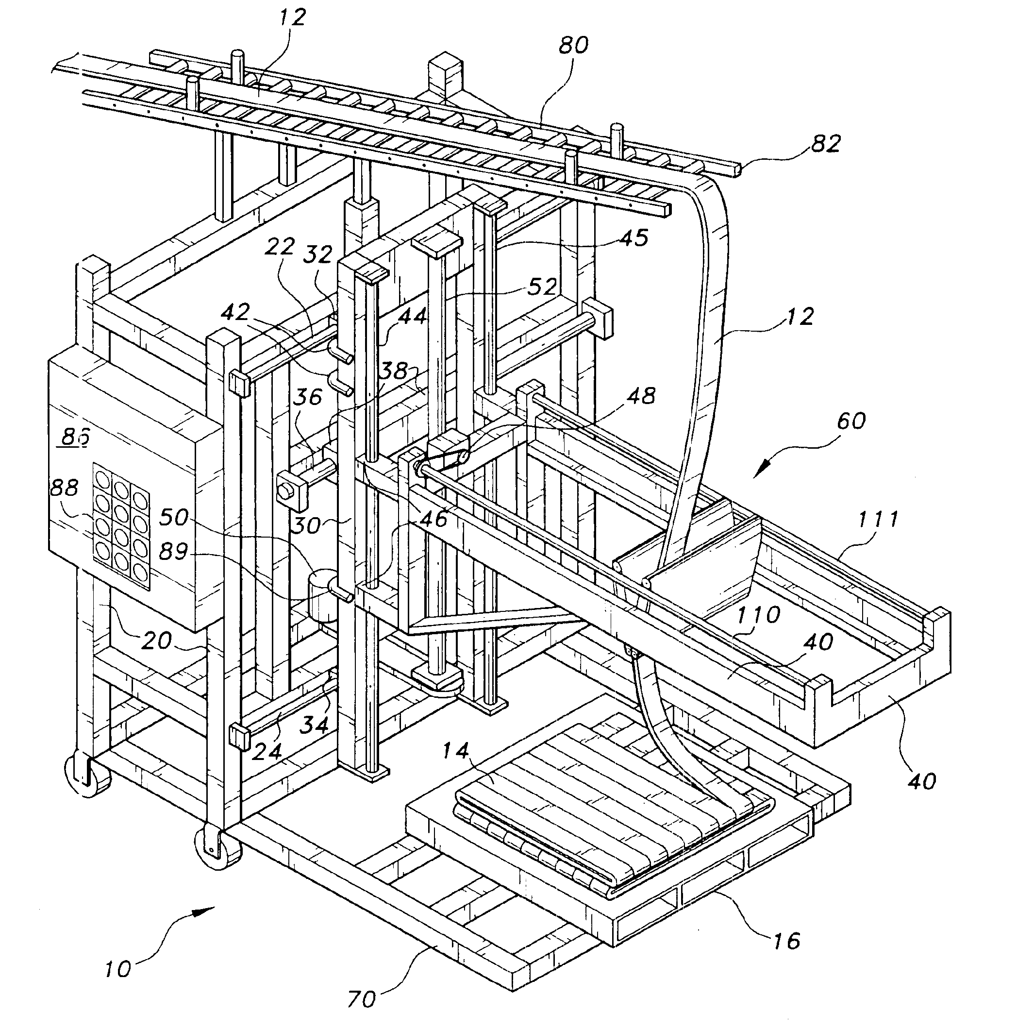
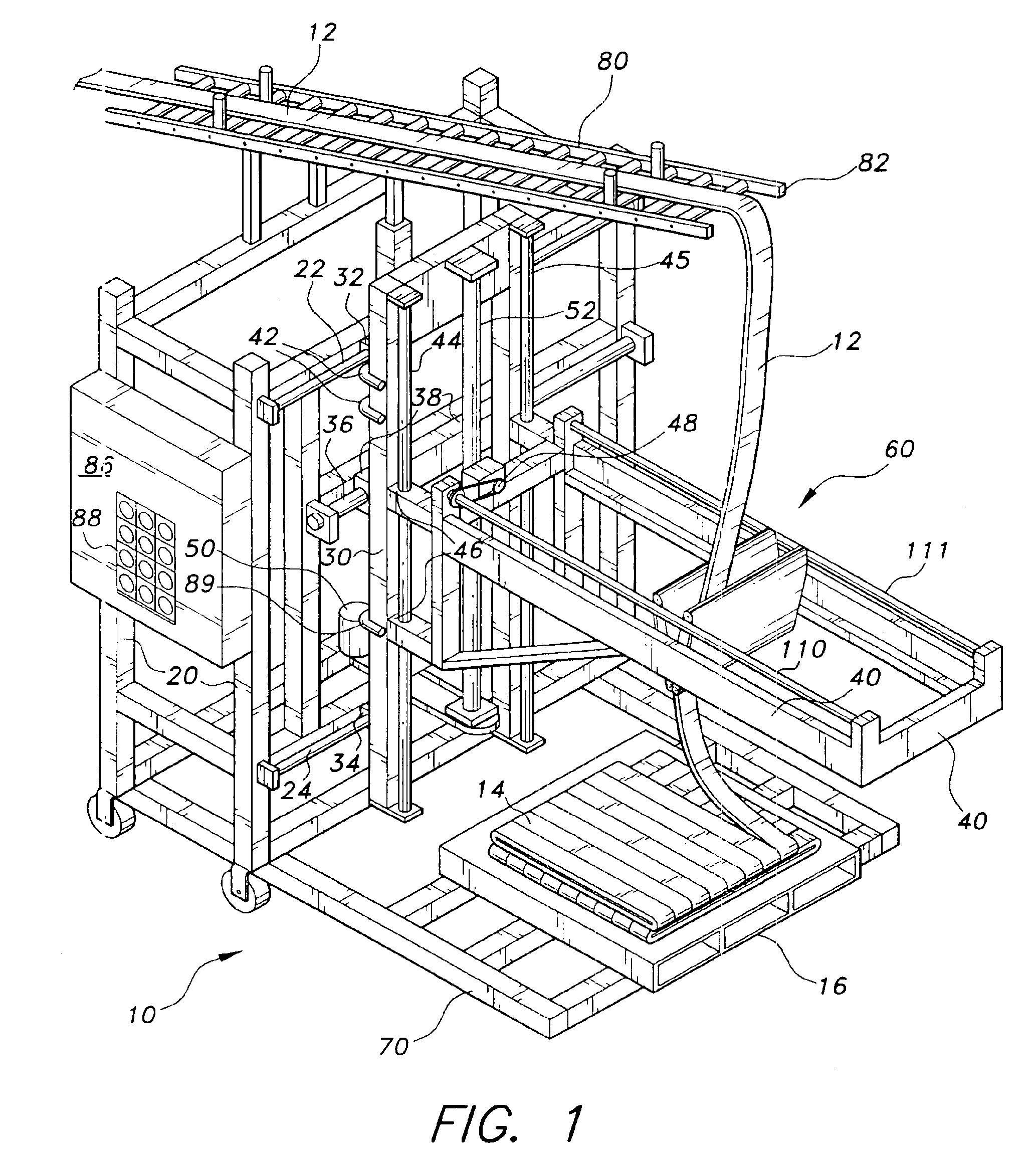
The present invention is an automated reciprocal stacking assembly for a relatively thin and flexible continuous sheet of stock material. The automated reciprocal stacking assembly is particularly adapted for stacking continuous strips of rubber on pallets during the manufacture of tires, but is not limited to being used in this manner and may be used for any appropriate application. The present automated reciprocal stacking assembly will be useful for stacking any other materials with similar characteristics and dimensions as the sheet rubber.

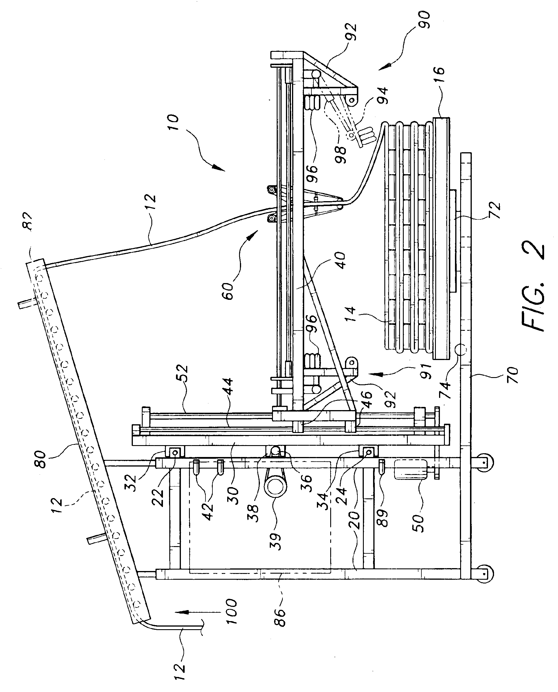
FIG. 1 depicts an environmental, perspective view of an automated reciprocal stacking assembly 10 according to the present invention. The moving components of the automated reciprocal stacking machine 10 extend from a stationary, vertical outer frame 20. The outer frame 20 is made from any suitable, sturdy structural material including, but not limited to, steel, rectangular tubing, angle or channel beams. The outer frame 20 provides support f...


PUM


Abstract

An automated reciprocal stacking assembly for stacking thin, narrow, continuous sheets of stock material. The automated reciprocal stacking assembly has a stationary outer frame, a laterally reciprocating inner frame, a vertically moveable carriage, a reciprocating distribution head, a base member, a pair of sheet retaining arms, a rotating platform for supporting a pallet and a conveyor belt. The reciprocating distribution head comprises a pair of feeding belts that are driven by a positive timing belt. The continuous sheet of stock material is supplied to the reciprocating distribution head by the conveyor through a large opening between the feeding belts of the reciprocating distribution head. The oppositely moving feeder belts force the stock material out of the reciprocating distribution head and onto a pallet.

Description

BACKGROUND OF THE INVENTION1. Field of the InventionThe present invention relates to automated material handling devices, and more particularly to an automated, multi-belt distribution head reciprocating stacker for sheet, strip material.2. Description of the Related ArtRubber is often manufactured in the form of a thin and narrow sheet of material. The thin, narrow rubber sheets are commonly produced in a continuous manner resulting in an extremely long sheet of rubber. It is not possible to store, package or transport the rubber in long flat sheets, so the rubber is commonly folded into a multilayer pile and stacked on a pallet for storage and shipping. The rubber sheet may be folded and stacked onto the pallets by hand, but this is an inefficient process. Many devices are used to automate the process of folding the rubber sheets. These stacking and folding devices commonly comprise an assembly of conveyor belts and distribution heads to evenly stack the rubber sheets onto managea...

Claims


Application Information

Patent Timeline
IPC IPC(8): B65H45/00B65H54/00B65H54/78B65H45/105
CPCB65H45/105B65H54/78B65H2301/42114
Inventor FRITZ, CHARLES W.MULDER, REIN
Owner FRITZ CHARLES W
Why Eureka
Try Eureka