Method and apparatus for repairing a riser brace in nuclear reactor

a technology for nuclear reactors and riser braces, applied in heterogeneous reactors, doors/windows, building scaffolds, etc., can solve the problems of real potential for excessive radiation exposure to personnel, substantial amount of piping to be replaced or repaired, and adversely affecting the safety of bwrs. , to achieve the effect of increasing the natural vibration frequency of the riser brace assembly

Inactive Publication Date: 2005-02-22
GENERAL ELECTRIC CO
View PDF2 Cites 41 Cited by
  • Summary
  • Abstract
  • Description
  • Claims
  • Application Information

AI Technical Summary

Benefits of technology

The present invention provides a method and apparatus for repairing a riser brace assembly in a reactor pressure vessel of an operating BWR. In an embodiment, the apparatus includes a clamp apparatus designed to structurally replace a weld (e.g., attaching a riser brace assembly to a reactor vessel wall); and to stiffen an entire riser brace assembly, thereby increasing the natural vibration frequency of the riser brace assembly. Installation of the clamp apparatus should not require removal of any installed reactor hardware, such as jet pump assembly hardware or shroud repair hardware.

Problems solved by technology

Separation of the riser brace 40 near this weld area could adversely impact safety in BWRs.
If just one jet pump assembly is damaged, a substantial amount of piping must either be replaced or repaired.
Since weld repairs in the downcomer annulus 28 area are typically not practical due to inaccessibility, and the potential for excessive radiation exposure to personnel is real, a need exists for a method and apparatus of repairing cracked riser braces involving little or no in-vessel machining.

Method used


Image

  • Method and apparatus for repairing a riser brace in nuclear reactor
  • Method and apparatus for repairing a riser brace in nuclear reactor
  • Method and apparatus for repairing a riser brace in nuclear reactor

Examples


Embodiment Construction

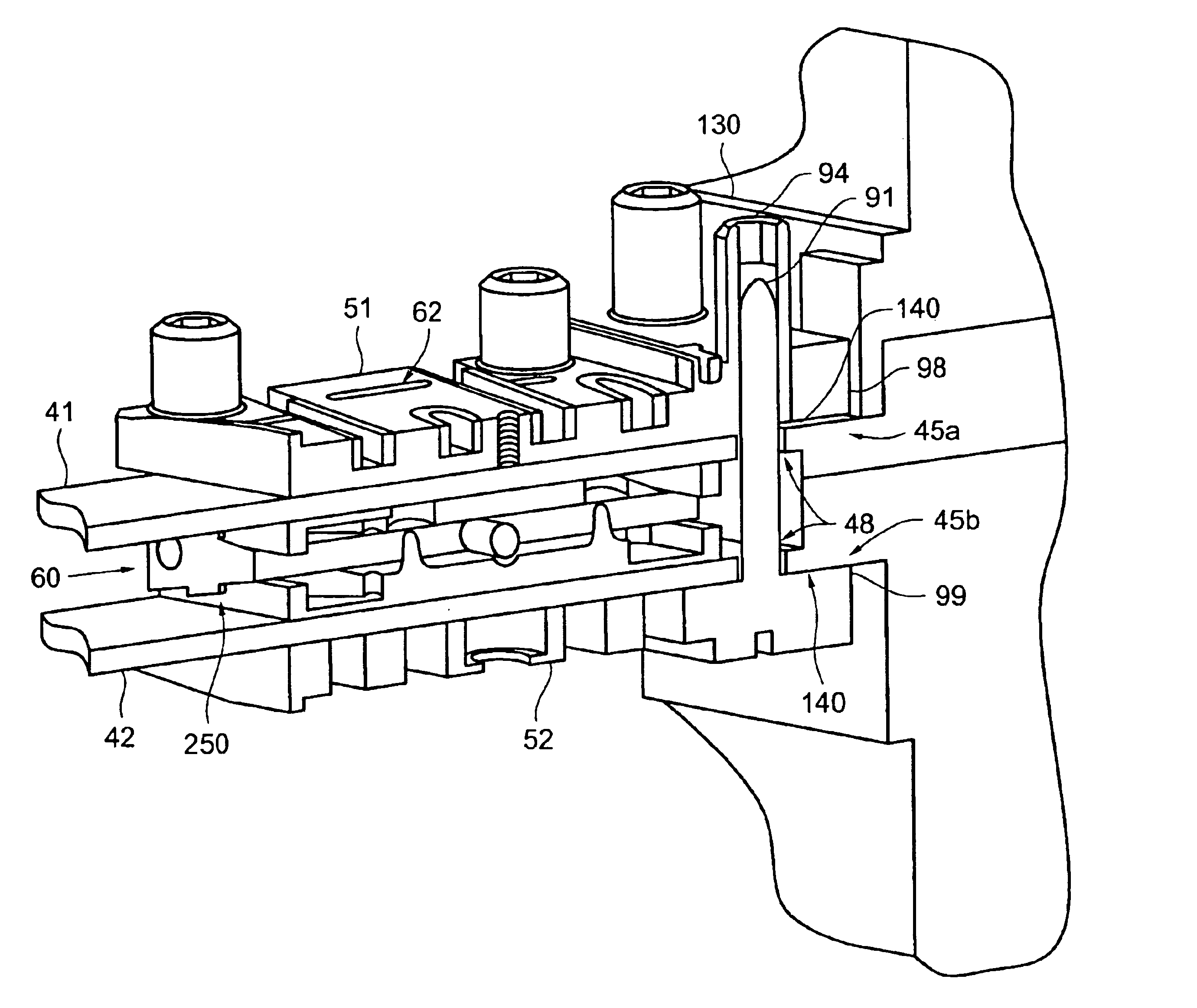
A riser brace repair clamp apparatus in accordance with the invention is designed to (1) structurally replace a weld attaching an upper riser brace leaf and / or a lower riser brace leaf to a reactor vessel wall at a riser brace block; and to (2) stiffen an entire riser brace assembly, thereby increasing the natural vibration frequency of the riser brace assembly. In general, the installation involves electric discharge machining (EDM) a location near a riser brace assembly / RPV sidewall interface in preparation for installing the riser brace clamp apparatus, assembling the hardware in the reactor, and preloading and locking a plurality of mechanical fasteners to secure riser brace clamp apparatus in place.

In order for the riser brace repair clamp apparatus to interface with an RPV sidewall, dual-tapered grooves are machined by EDM in an upper surface and a lower surface of a riser brace block that is part of the riser brace assembly. These grooves receives tongue portions from a top p...


PUM


Abstract

A clamp apparatus is provided which is designed to structurally replace a weld that attaches a riser brace assembly to a reactor vessel wall, and to stiffen the entire riser brace assembly, thereby increasing the natural vibration frequency of the riser brace assembly. Installation of the clamp apparatus should not require removal of any installed reactor hardware, such as jet pump assembly hardware or shroud repair hardware. In an embodiment, the clamp apparatus may include a first plate arranged so as to mate with a first groove on the riser brace, and a second plate arranged so as to mate with a second groove on the riser brace. The grooves provide alignment for the clamp apparatus, so that the first and second plates can be fixedly secured to the riser brace.

Description

BACKGROUND OF THE INVENTION1. Field of the InventionThis invention relates generally to nuclear reactors and, more particularly, to a method and apparatus for repairing a riser brace that lends lateral support to a jet pump assembly of a boiling water reactor.2. Related ArtA reactor pressure vessel (RPV) of a boiling water reactor (BWR) typically has a generally cylindrical shape and is closed at both ends, e.g., by a bottom head and a removable top head. A top guide typically is spaced above a core plate within the RPV. A core shroud, or shroud, typically surrounds the core and is supported by a shroud support structure. Particularly, the shroud has a generally cylindrical shape and surrounds both the core plate and the top guide. There is a space or annulus located between the cylindrical reactor pressure vessel and the cylindrically-shaped shroud.FIG. 1 is a schematic, partial cross sectional view, with parts cut away, of a reactor pressure vessel (RPV) 20 for a boiling water rea...

Claims


Application Information

Patent Timeline
Patent Type & Authority Patents(United States)
IPC IPC(8): F16B2/02F16B2/14F16G11/00G21C15/25G21C15/00G21C19/02G21C1/08
CPCG21C1/084G21C15/25Y10T403/7067Y02E30/31Y10T403/16G21Y2004/50Y02E30/30
Inventor JENSEN, GRANT C.
Owner GENERAL ELECTRIC CO
Why Eureka
Try Eureka