Cable structure with improved grounding termination in the connector

a technology of grounding termination and cable structure, which is applied in the direction of connection contact member material, two-part coupling device connection, and connection device connection, etc., can solve the problems of large or bulky connector structure, large size of connector structure, and general less robust design. , to achieve the effect of improving the signal integrity of the cable structure, reducing the possibility of signal conductor shorting to ground, and keeping the size of the connector structure suitably compa

Inactive Publication Date: 2005-02-22
CARLISLE INTERCONNECT TECH
View PDF99 Cites 42 Cited by
  • Summary
  • Abstract
  • Description
  • Claims
  • Application Information

AI Technical Summary

Benefits of technology

The cable structure of the invention maintains the signal conductors and ground conductors within separate, spaced planes to improve the signal integrity of the cable structure and reduce the possib

Problems solved by technology

However, depending upon the number of conductors within a cable structure, such an arrangement may require a large or bulky connector structure.
While the goal of utilizing a single ground reference for multiple ground conductors within a cable structure is achieved, prior designs have had significant drawbacks.
First, such designs are generally less robust due to the score lines between the conductive-ground contacts and carrier strip.
Movement of the cable and manipulation of the connector may cause physical separation of the ground strips at the score line, thus creating an open circuit condition at the ground contacts.
Furthermore, during the manufacturing of a cable structure utilizing such a connector design, an additional and costly step is involved to detach any non-ground contacts from the carrier strip and to insure that the grounded c

Method used


Image

  • Cable structure with improved grounding termination in the connector
  • Cable structure with improved grounding termination in the connector
  • Cable structure with improved grounding termination in the connector

Examples


Embodiment Construction

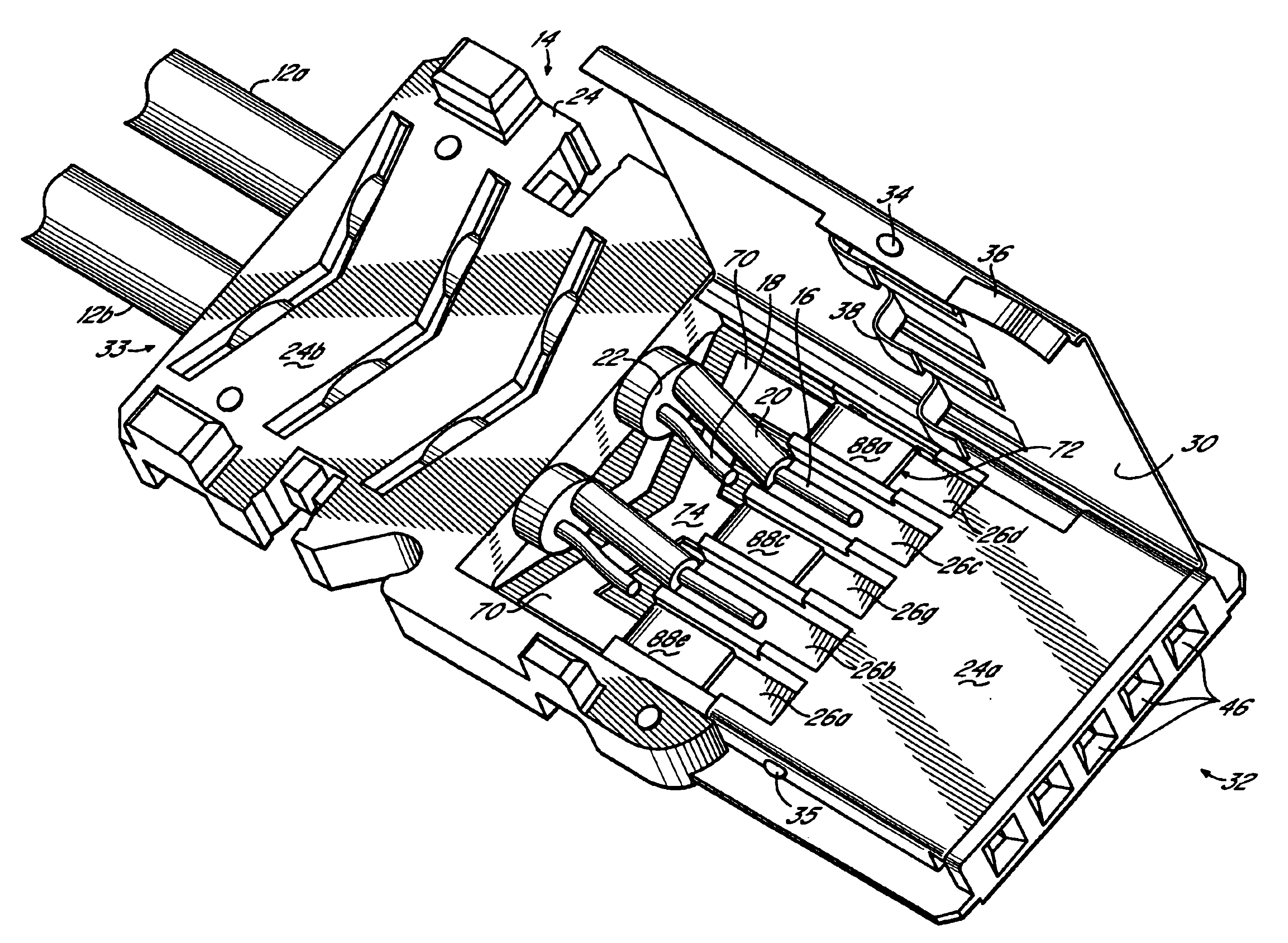
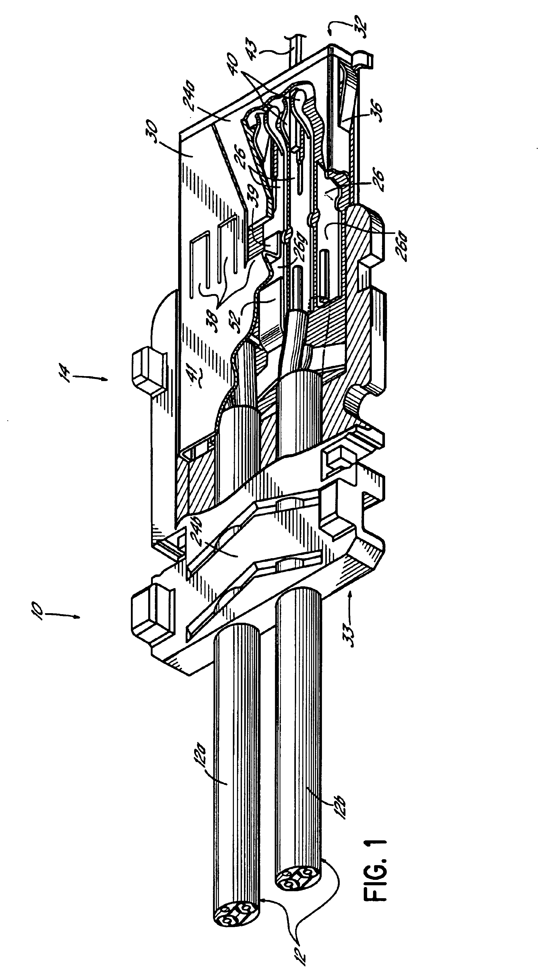
FIG. 1 is a perspective view, partially cut away, illustrating one embodiment of the present invention. Cable structure 10 comprises one or more cable portions or transmission lines 12 terminating in a connector 14. In the embodiment illustrated in FIG. 1, two transmission lines 12a, 12b terminate in the connector 14. A single transmission line could be utilized in the invention, or a greater number of transmission lines than those shown in FIG. 1 may also be utilized in accordance with the principles of the present invention.

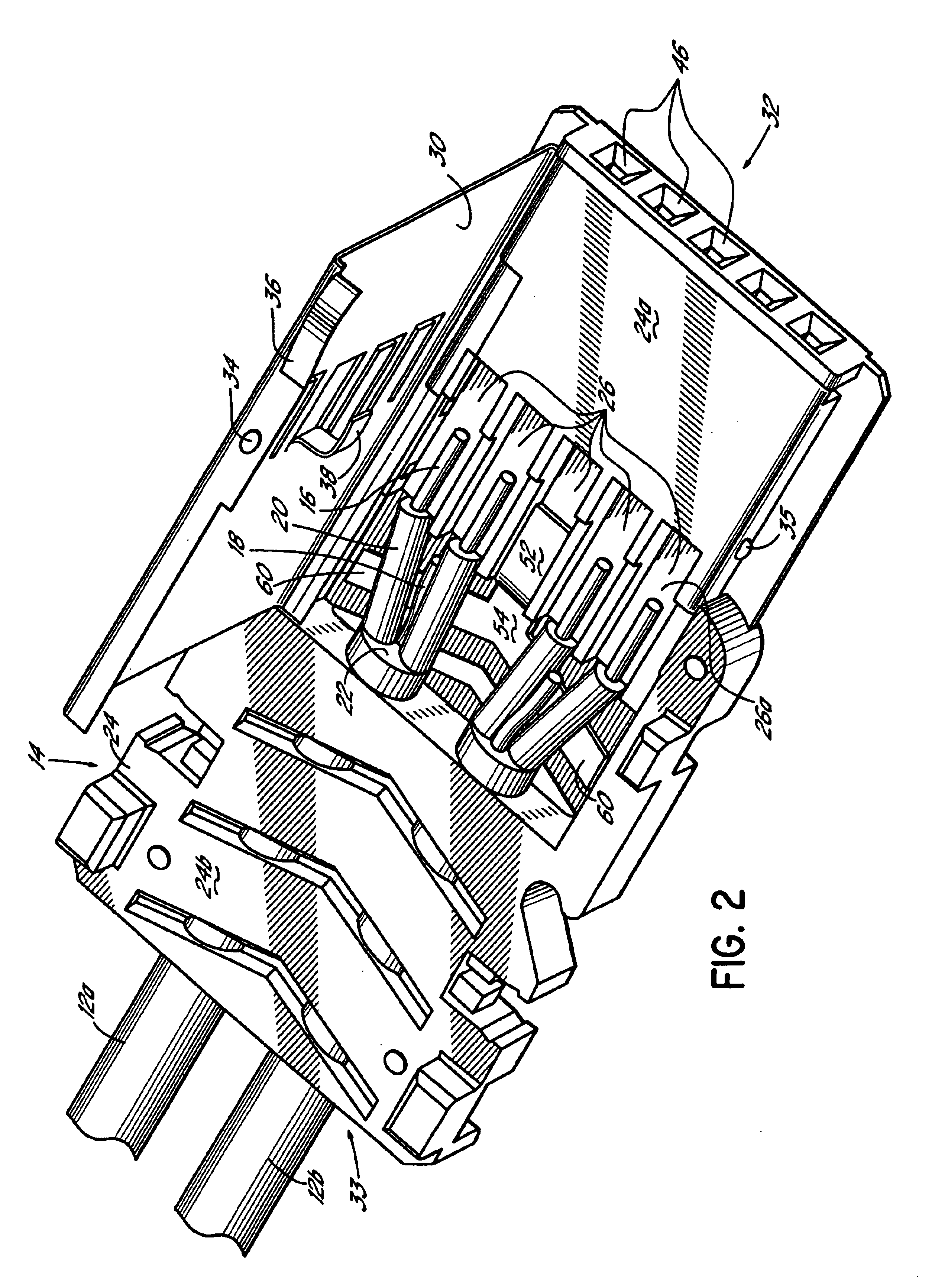
Referring to FIG. 2, each of the transmission lines 12 includes multiple signal conductors 16 and a ground conductor 18. The ground conductor 18 is often referred to as a drain wire. Suitable conductors for the invention are formed of wires such as multi-stranded copper wires, although solid copper wires might also be utilized. Each of the signal conductors 16 are separately insulated by insulation 20, which may be extruded onto the conductors. The signal condu...


PUM


Abstract

A cable structure for signal transmission comprises a connector housing and a plurality of housing contacts positioned within a defined contact plane in the connector housing. The housing contacts are configured for engaging external contacts of a device when the cable structure is coupled to a device. At least one signal conductor terminates in the connector housing, and is electrically coupled to one of the housing contacts generally in said contact plane. At least one ground conductor terminates in the connector housing, in a second plane spaced from the contact plane. A shorting bar has a first portion positioned generally in said contact plane and electrically coupled to a housing contact. A second portion of the shorting bar is positioned generally in said second plane and is electrically coupled to the ground conductor. The shorting bar maintains the signal conductor and ground conductor termination within separate spaced planes to improve the signal integrity of the cable structure while keeping the housing contacts in a common plane.

Description

FIELD OF THE INVENTIONThis present invention relates generally to signal transmission cable structures for electronic devices and particularly to improving the performance and construction of such a cable structure by improving the ground termination at the connector of the cable structure.BACKGROUND OF THE INVENTIONThe use of electronic devices of all kinds has increased dramatically throughout society, which has led to a significant increase in the demand for improved components utilized with such devices. One facet in the utilization of such electronic devices involves the data communications between such devices within a networked system. For example, many electronic devices may now be coupled and synchronized with other electronic devices, such as a computer, for transmitting data and other information back and forth between the various devices.For accurate data and information transmission in such a system, the components of the system devices, and particularly the interface c...

Claims


Application Information

Patent Timeline
IPC IPC(8): H01R12/24H01R12/00H01R12/70
CPCH01R23/662H01R13/6593
Inventor REED, BRUCETUTT, CHRISTOPHER A.
Owner CARLISLE INTERCONNECT TECH
Why Eureka
Try Eureka